

Capacitor and manufacturing method therefor
A manufacturing method and capacitor technology, applied in the direction of electrolytic capacitor manufacturing, capacitors, electrolytic capacitors, etc., can solve problems such as damage to the low height of capacitors, and achieve the effects of improving configuration accuracy, improving bending accuracy, and preventing back-bending
- Summary
- Abstract
- Description
- Claims
- Application Information
AI Technical Summary
Problems solved by technology
Method used
Image

Examples
no. 1 Embodiment approach
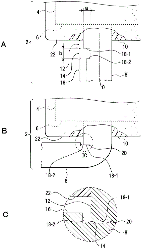
[0037] figure 1 A of A shows a part of the capacitor of the first embodiment. figure 1 The structure shown by A is an example, and this invention is not limited to this structure.
[0038] The capacitor 2 is, for example, a solid electrolytic capacitor and is an example of the capacitor of the present invention.
[0039] For this capacitor 2, for example, a capacitor element 4 wound into a cylindrical shape is used. In this capacitor element 4 , as an example, an anode-side electrode foil, a first separator, a cathode-side electrode foil, and a second separator are laminated, wound into a cylindrical shape, and then impregnated with an electrolyte. The electrode foil on the anode side of the capacitor element 4 is connected to an anode-side lead terminal, and the electrode foil on the cathode side is connected to a cathode-side lead terminal. These lead terminals are led out from the element end face 6 of the capacitor element 4 . The illustrated lead terminal 8 may be e...
no. 2 Embodiment approach
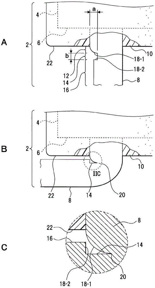
[0051] figure 2 A in the figure shows the capacitor 2 of the second embodiment. exist figure 2 of A, pair with figure 1 The same parts of A are given the same reference numerals.
[0052] In the first embodiment, the stretching portion 12 is rod-shaped with the same diameter, whereas in the second embodiment, it has a hemispherical curved portion. Therefore, the level difference part 18-1 is formed with a curved surface.
[0053] According to this structure, on the lead terminal 8, since the step portion 18-1 does not have a corner but a curved surface, as shown in FIG. figure 2 As shown in B, the bent portion 20 is formed by bending the lead terminal 8 with the corner portion serving as the boundary portion between the stepped portion 18 - 1 and the notch 14 as the bending starting point. During this bending, the stepped portion 18-1 is deformed along with the formation of the bent portion 20, thereby avoiding the stepped portion 18-2 and avoiding the interference of...
no. 3 Embodiment approach
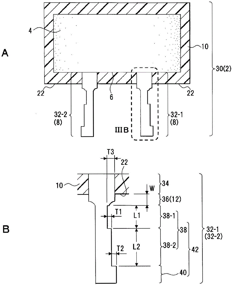
[0061] image 3 A shows a cross section of a solid electrolytic capacitor. image 3 The structure shown by A is an example, and this invention is not limited to this structure.
[0062] Conventionally, in the lead terminal, the length of the stretched part generated during the flattening process was different, so even if it was bent along the outer surface of the resin layer, the length of the stretched part would not be parallel to the outer surface of the resin layer. , there may be deviations in the height of the capacitor.
[0063] In addition, when the lead terminal is flattened in order to maintain the stability of the substrate layout, the desired portion is flattened. There is a stretch between them. The boundary between the stretched portion and the flat surface becomes the bending position. Due to the difference in the length of the stretched part, there will also be deviations in the bending position. When the stretched portion is long and the position away fro...
PUM
 Abstract
Description
Claims
Application Information