Remaining needle with elastic contact

A technology of elastic contacts and indwelling needles, which is applied in the field of indwelling needles, can solve problems such as easy swing on the indwelling needle seat, blood backflow, and thrombus formation, so as to reduce the increase in medical expenses, prolong the use time, and prevent blood backflow Effect

Active Publication Date: 2015-09-23
陈伟权
View PDF10 Cites 4 Cited by
  • Summary
  • Abstract
  • Description
  • Claims
  • Application Information

AI Technical Summary

Problems solved by technology

However, due to the fact that the existing liquid stop clamp will have a rebound after the clip of the liquid stop clamp is loosened in the process of clamping the extension hose, the original clamped extension hose will form a The elastic rebound causes the blood to flow back into the indwelling tube, causing the blood to flow back and form a thrombus, which affects the performance of the indwelling needle
At the same time, because the tip of the indwelling hose is open, pressure fluctuations caused by changes in the patient's breathing and heartbeat will also cause blood backflow and platelets and coagulation substances to enter the indwelling hose, causing coagulation to block the tube, especially due to the hemostatic clip Actively installed on the extension tube, during the process of completing the infusion and stopping the liquid, the liquid stop clip is easy to swing on the indwelling needle seat, causing the liquid in the extension tube to produce a siphon effect and suck the blood in the blood vessel back to the indwelling soft tube. In the tube, the blood backflow will cause thrombus to form, which seriously affects the use time of the indwelling needle. Therefore, the existing indwelling needle can only be used for 1-2 days, and the indwelling needle must be removed and replaced with a new one due to the formation of thrombus.

Method used


Image

  • Remaining needle with elastic contact
  • Remaining needle with elastic contact
  • Remaining needle with elastic contact

Examples


Embodiment Construction

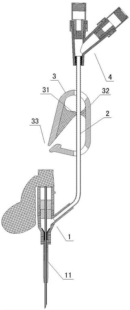
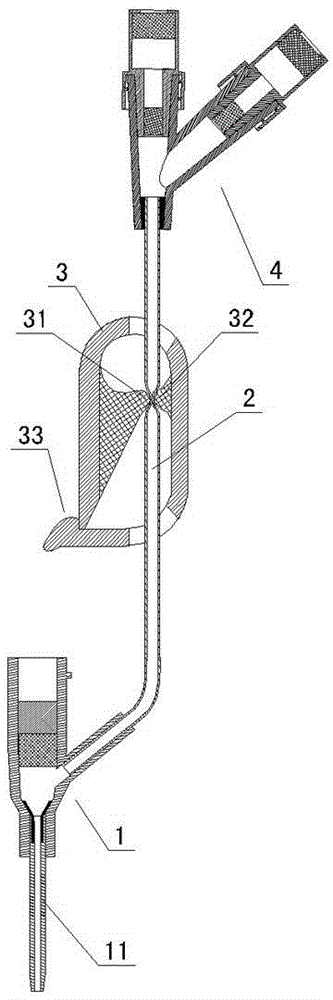
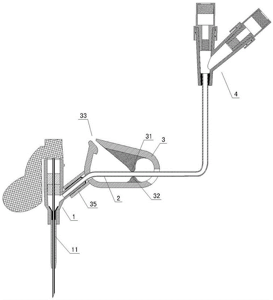
[0018] like Figure 1 to Figure 8 As shown, an indwelling needle with an elastic contact according to the present invention includes an indwelling hose 11, an indwelling needle base 1, an extension tube base 4, and an extension hose connected between the indwelling needle base 1 and the extension tube base 4 2. The liquid stop clip 3 installed on the extension hose 2, at least one of the upper contact 31 and the lower contact 32 of the liquid stop clip 3 pressing part is made of a different rigid body than the liquid stop clip 3 The elastic contact that can form a continuous positive pressure on the extension hose 2. The structure of the upper contact 31 and the lower contact 32 of the pressing part of the above-mentioned liquid stop clip 3 is varied, and can be as follows: Figure 1 to Figure 6 As shown, the upper contact 31 and the lower contact 32 of the pressing part of the liquid stop clip 3 are elastic point-like elastic contacts that can form continuous positive ...


PUM


Abstract

A remaining needle with an elastic contact comprises a remaining soft pipe, a remaining needle base, an extending pipe base, an extending soft pipe connected between the remaining needle base and the extending pipe base and a liquid stopping clamp arranged on the extending soft pipe. The remaining needle is characterized in that at least one of an upper contact and a lower contact of a pressing-contacting part of the liquid stopping clamp is an elastic contact which can form continuous positive pressure on the extending soft pipe with different liquid stopping clamp hard bodies. The liquid stopping clamp structure with the elastic contact is used, the elastic pressure between the upper contact and the lower contact is larger than human body venous pressure, blood back flowing is effectively prevented, the extending pipe is clamped, and the problem that liquid at the back end enters the remaining soft pipe is avoided. When large external force is applied to the back end of the extending pipe and the external force is larger than the pressure between the elastic contacts of the liquid stopping clamp, the elastic contacts can be slightly stretched so that high-pressure liquid in the back portion of a cavity of the extending pipe can pass, positive pressure is formed in the remaining soft pipe and a front cavity of the extending pipe, and blood flowing back into the remaining soft pipe is forced to flow back to into a blood vessel.

Description

technical field [0001] The invention relates to an indwelling needle and belongs to the technical field of medical instruments. Background technique [0002] Existing indwelling needles generally include an indwelling hose, an indwelling needle base, an extension tube base, an extension hose connected between the indwelling needle base and the extension tube base, and a liquid stop clip installed on the extension hose. The liquid stop clamp generally includes a clamp seat and a clip piece integrated on the clamp seat. The clamp seat is placed on the extension hose, and the extension hose can be clamped to form a liquid stop through the cooperation of the clip piece and the clamp seat. However, due to the fact that the existing liquid stop clamp will have a rebound after the clip of the liquid stop clamp is loosened in the process of clamping the extension hose, the original clamped extension hose will form a The elastic rebound causes the blood to flow back into the in...

Claims


Application Information

Patent Timeline
Patent Type & Authority Applications(China)
IPC IPC(8): A61M5/158
CPCA61M5/158A61M2005/1586
Inventor 陈伟权江优
Owner 陈伟权
Why Eureka
Try Eureka