
Drainage structure of garment steamer and garment steamer

A drainage structure and technology of garment ironing machines, which are applied in laundry room devices, washing devices, wrinkle-removing and flattening equipment, etc., can solve problems such as residual water drainage difficulties, reduce bacterial growth, prolong service life, and improve satisfaction Effect

Active Publication Date: 2017-03-22
FOSHAN SHUNDE MIDEA ELECTRICAL HEATING APPLIANCES MFG CO LTD +1
View PDF6 Cites 0 Cited by
  • Summary
  • Abstract
  • Description
  • Claims
  • Application Information

AI Technical Summary

Problems solved by technology

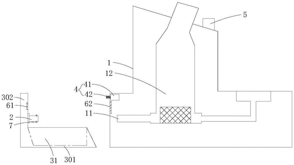
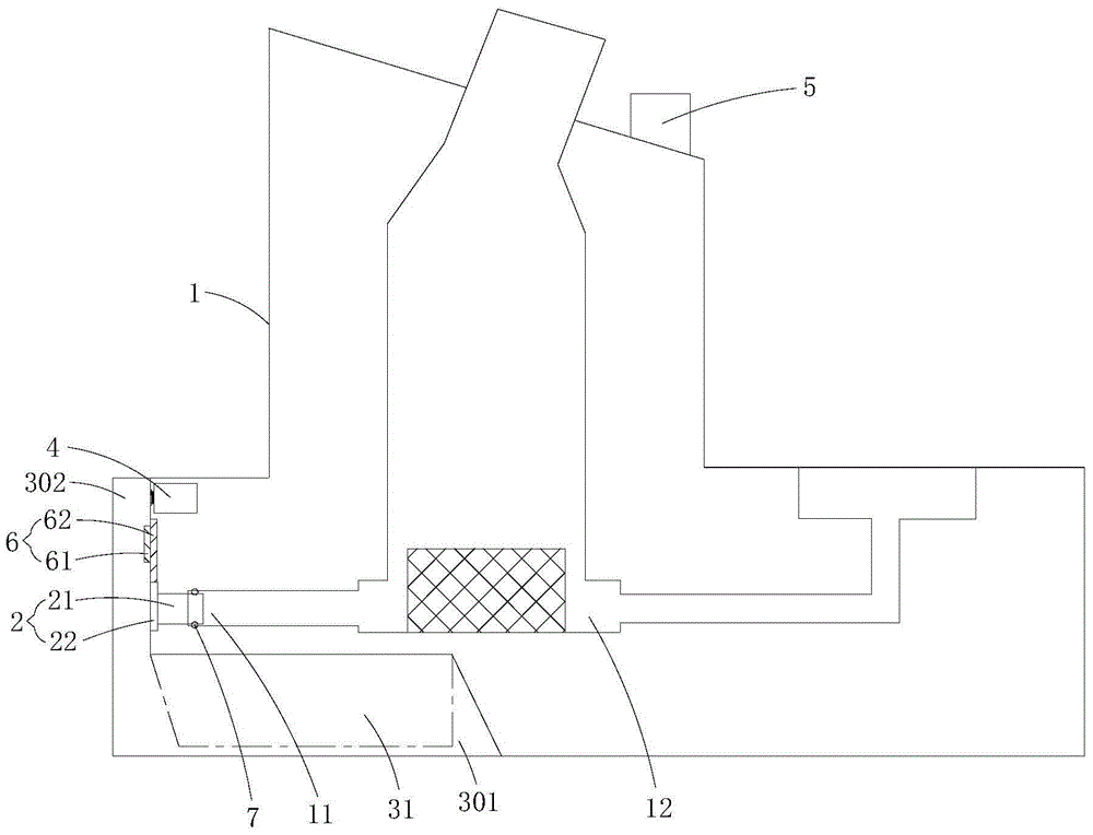
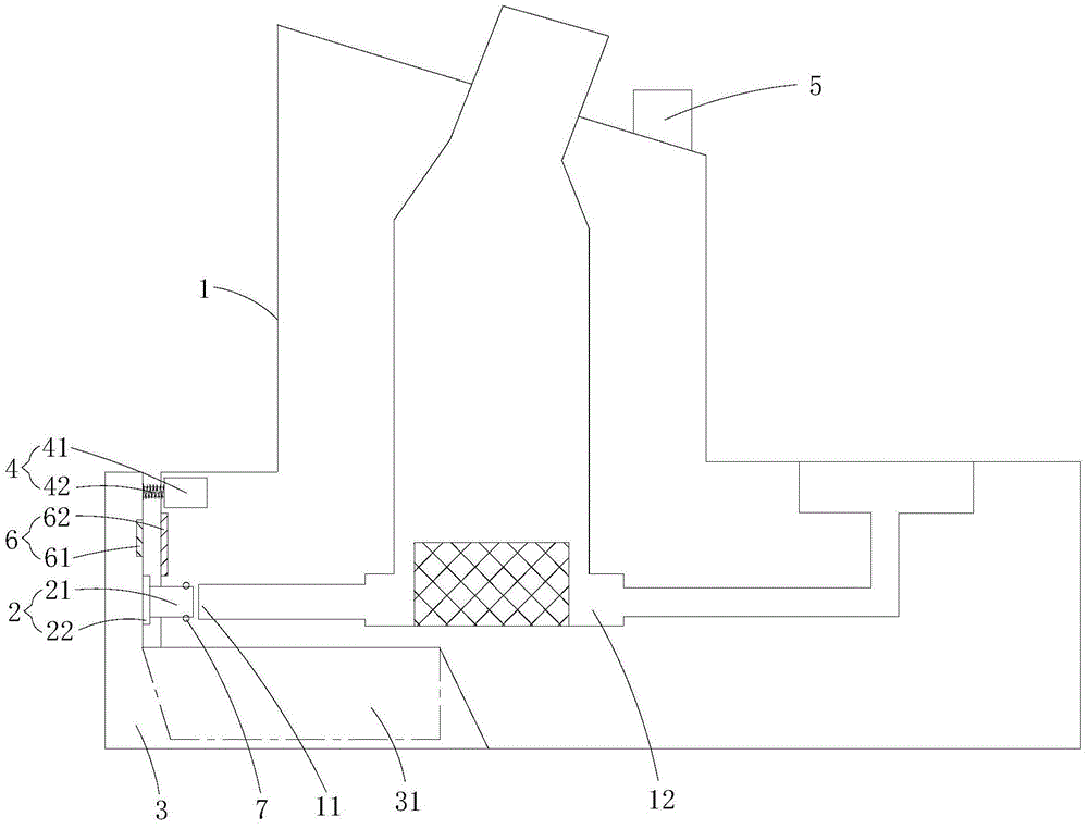
[0003] The purpose of the present invention is to overcome the above-mentioned deficiencies in the prior art, and provide a drainage structure for a garment steamer and a garment steamer, which solve the technical problem of difficulty in draining residual water in the internal water system of the existing garment steamer

Method used


Image

  • Drainage structure of garment steamer and garment steamer
  • Drainage structure of garment steamer and garment steamer
  • Drainage structure of garment steamer and garment steamer

Examples


Embodiment Construction

[0019] In order to make the object, technical solution and advantages of the present invention clearer, the present invention will be further described in detail below in conjunction with the accompanying drawings and embodiments. It should be understood that the specific embodiments described here are only used to explain the present invention, not to limit the present invention.

[0020] It should be noted that when an element is referred to as being “fixed” or “disposed on” another element, it may be directly on the other element or there may be an intervening element at the same time. When an element is referred to as being "connected to" another element, it can be directly connected to the other element or intervening elements may also be present.

[0021] It should also be noted that the orientation terms such as left, right, up, down, top, and bottom in the following examples are only relative concepts or refer to the normal use status of the product, and should not be ...


PUM


Abstract

The invention is applicable to the field of clothing treatment devices and discloses a drainage structure of a garment steamer and a garment steamer. The drainage structure of the garment steamer includes a main body with a drainage outlet and a drainage control for controlling the switch of the drainage outlet. Water storage on the main body box, a push-pull member fastened to the main body for pushing the water storage box away from the main body, and a controller for electrically controlling the push-pull member. The water storage box has a storage tank for water discharged from the drain outlet to flow into it. Water cavity, drainage control is installed on the water storage box. In the present invention, by operating the controller, the push-pull component can be moved and the water storage box and the drainage control can be pushed away from the main body, thereby opening the drainage outlet, thereby allowing the residual water in the waterway system inside the main body to be automatically discharged from the drainage outlet into the storage tank. In the water storage cavity of the water box, finally, you only need to disassemble the water storage box from the main body and pour out the water in the water storage box. The pouring process is very simple and convenient.

Description

technical field [0001] The invention belongs to the field of clothes processing devices, and in particular relates to a drainage structure of a garment steamer and a garment steamer with the drainage structure of the garment steamer. Background technique [0002] After the garment steamer is used, the residual water in the internal water system of the main body needs to be drained, otherwise it is easy to breed bacteria, produce scale and other undesirable phenomena, which will affect the performance of the garment steamer. However, in the prior art, the drainage structure of the garment steamer is not designed properly, so that every time it is necessary to discharge the residual water in the internal water system of the main body, it is necessary to hold the main body to the side of the pool first, and then pass the drainage. pour water out of the mouth; because the position and size of the drain outlet of different types of garment steamers are also different, and the wei...

Claims


Application Information

Patent Timeline
Patent Type & Authority Patents(China)
IPC IPC(8): D06F73/00
CPCD06F73/00
Inventor 梁志斌梁汉卫刘化勇谢波雷红艳
Owner FOSHAN SHUNDE MIDEA ELECTRICAL HEATING APPLIANCES MFG CO LTD
Learn More