High efficient wax-prevention viscosity reduction and oil increasing apparatus

A wax-prevention and viscosity-reducing technology, applied in the fields of production fluids, wellbore/well components, earthwork drilling, etc., can solve the problems of heavy pumping unit workload, difficult oil production operations, and high wax content in crude oil, and increase the flow of crude oil. capacity, reducing the number of well flushes, and increasing the effect of oil well production

Inactive Publication Date: 2015-09-23
黄石市新科石油机械配件厂(普通合伙)
View PDF2 Cites 2 Cited by
  • Summary
  • Abstract
  • Description
  • Claims
  • Application Information

AI Technical Summary

Problems solved by technology

[0002] Generally, crude oil has high wax content, high viscosity, and poor fluidity, which brings great difficulties to oil production operations.
Someone invented a strong magnetic treatment wax preventer to decompose the paraffin in crude oil, but the effect was not ideal after experiments, because the magnetic circuit was unreasonable and the magnet material was selected incorrectly. In the past, pairs of tile-shaped magnets formed along the inner wall of the tube For forming a helical arrangement with a length of about 300mm, the field strength is smaller and the gradient is smaller, and the paraffin molecules cannot be arranged in one direction
The effect is not good
Moreover, the single anti-wax function cannot solve the problem of high viscosity and poor fluidity of crude oil, which makes the work load of the pumping unit heavy.
For this reason, the inventor of the present application once invented a kind of anti-wax demagnetization and oil-increasing device, and has obtained a national patent, the patent number is 200520095426.6. This invention has played a certain effect on solving the problems of high viscosity and poor fluidity of crude oil
After popularization and use in recent years, it is found that the device of the invention is not very ideal, and there is still room for improvement in its anti-wax and anti-sticking and oil-increasing effect.

Method used


Image

  • High efficient wax-prevention viscosity reduction and oil increasing apparatus
  • High efficient wax-prevention viscosity reduction and oil increasing apparatus
  • High efficient wax-prevention viscosity reduction and oil increasing apparatus

Examples


Embodiment Construction

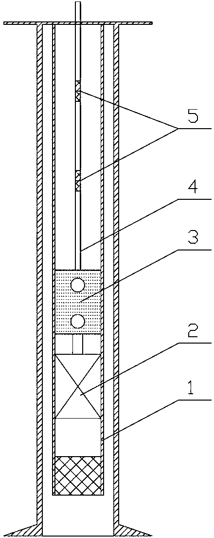
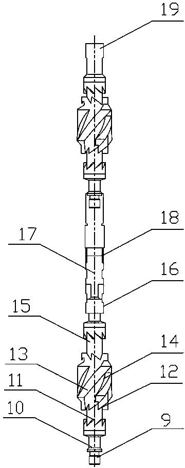
[0017] see figure 1 , the present invention includes a sucker pipe 1 and a sucker rod 4, a sucker pump 3 is installed at the lower end of the sucker rod 4, and a primary anti-wax viscosity-reducing oil booster 2 is installed at the lower end of the sucker rod, especially: 4 The lower section is close to the oil well pump 3, and at least one set of rod-type swirl magnets 5 is plugged in. The rod-type swirl magnets (see image 3 ) has a connecting rod 17, and a swirl centralizer is installed at the upper and lower ends of the connecting rod; the swirl centralizer includes a mandrel 15, a centralizer 13 is installed in the middle of the mandrel, and 2-4 heads are arranged on the outer wall of the centralizer Spiral groove 14, the two ends of the centralizer are in a straight zigzag shape 12, and the serrations 12 on both end surfaces are oppositely inclined, and left and right stop sleeves 10 and 16 are designed at both ends of the mandrel, and the stop sleeves face the end faces...


PUM


Abstract

The invention relates to the industry of petroleum exploitation and provides a high efficient wax-prevention viscosity reduction and oil increasing apparatus applied to underwell oil pumping. The apparatus comprises an oil pumping pipe and an oil pumping rod, wherein the lower end of the oil pumping rod is equipped with an oil pump; and the lower end of the oil pump is connected with a primary wax-prevention viscosity reduction oil increasing device. The high efficient wax-prevention viscosity reduction and oil increasing apparatus is characterized in that at least one sleeve rod type eddy flow strong magnetic device is inserted into a place where the lower section of the oil pumping rod is close to the oil pump; the rod type eddy flow strong magnetic device is provided with a connection rod; the middle part of the connection rod is covered with a magnetic ring set; the magnetic ring set is formed by at least three overall magnetic rings overlapped; same magnetic poles of opposite surfaces of each two overall magnetic rings are arranged; a splicing magnetic ring is inserted in each two overall magnetic rings; the same magnetic rings of two sector-shaped magnetic blocks oppositely arranged are arranged facing each other; and a coat is arranged outside the magnetic ring set to integrate all the magnetic rings into one. By the use of the high efficient wax-prevention viscosity reduction and oil increasing apparatus, crude oil viscosity can be reduced, wax precipitation can be prevented, flow capability can be increased and oil well production amount can be increased, so the apparatus is suitable for various oil production wells, such as plumb wells, inclined wells and horizontal wells.

Description

technical field [0001] The invention relates to industrial equipment for oil exploitation, in particular to a high-efficiency wax-preventing, viscosity-reducing, oil-increasing device. Background technique [0002] Generally, crude oil has high wax content, high viscosity, and poor fluidity, which brings great difficulties to oil production operations. Someone invented a strong magnetic treatment wax preventer to decompose the paraffin in crude oil, but the effect was not satisfactory after experiments, because the magnetic circuit was unreasonable, and the magnet material was selected incorrectly. In the past, pairs of tile-shaped magnets were formed along the inner wall of the tube. For forming a helical arrangement with a length of about 300mm, the field strength is smaller and the gradient is smaller, so the paraffin molecules cannot be arranged in one direction. The effect is not good. Moreover, the single anti-wax function cannot solve the problem of high viscosity a...

Claims


Application Information

Patent Timeline
Patent Type & Authority Applications(China)
IPC IPC(8): E21B43/285
Inventor 李震寰
Owner 黄石市新科石油机械配件厂(普通合伙)
Why Eureka
Try Eureka