Ball loading device of high-efficiency angular contact bearing

An angular contact bearing and ball loading technology, which is applied to bearing components, shafts and bearings, mechanical equipment, etc., can solve the problems of slow speed of steel balls, low production efficiency, and easy scratches of steel balls, so as to improve production efficiency and structure Simple, the effect of reducing bump damage

Inactive Publication Date: 2015-09-23
JIANGSU LIANDONG BEARING
View PDF8 Cites 9 Cited by
  • Summary
  • Abstract
  • Description
  • Claims
  • Application Information

AI Technical Summary

Problems solved by technology

At present, when installing steel balls, workers need to place the steel balls one by one in the pocket of the cage for assembly. The speed of placing the steel balls is relatively slow, and the production efficiency is low. At the same time, the steel balls are easy to scratch

Method used


Image

  • Ball loading device of high-efficiency angular contact bearing
  • Ball loading device of high-efficiency angular contact bearing

Examples


Embodiment Construction

[0014] The specific implementation manner of the present invention will be described below in conjunction with the accompanying drawings.

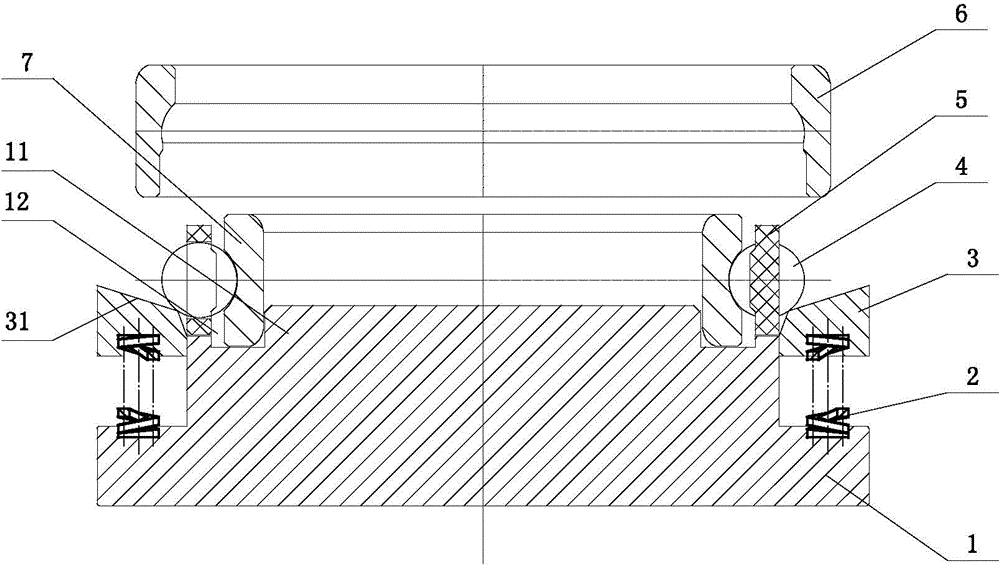
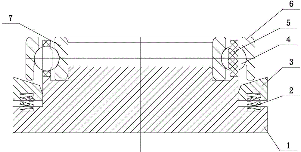
[0015] Such as figure 1 As shown, the ball loading device for high-efficiency angular contact bearings of this embodiment includes a base 1 with a convex structure, and a central boss 11 on its upper surface has a groove ring 12 for placing the inner ring 7 of the bearing. The inner wall of the groove ring 12 is in contact with the inner wall of the bearing inner ring 7. A guide ring 3 is installed on the periphery of the central boss 11. The lower surface of the guide ring 3 is connected to the base 1 through a plurality of springs 2. The upper surface of the guide ring 3 has a guide ring surface 31 inclined to the groove ring 12, and there is an installation gap for installing the bearing cage 5 between the guide ring 3 and the groove ring 12.

[0016] The inner edge of the guide ring surface 31 is higher than the lowest point of the st...


PUM


Abstract

The invention relates to a ball loading device of a high-efficiency angular contact bearing. The device comprises a base, wherein the base has a convex structure; a center boss on the upper surface thereof has a groove ring for placing a bearing inner ring; the inner side wall of the groove ring is contacted with the inner wall of the bearing inner ring; a guide ring is mounted at the periphery of the center boss; the lower surface of the guide ring is connected with the base through multiple springs; the upper surface of the guide ring has a guide ring surface inclined to the groove ring; and an installation gap for mounting a bearing retainer is formed between the guide ring and the groove ring. The device is simple in structure, and changes the traditional manual installation of steel balls to an automatic steel ball assembly mode through a guide structure to realize automatic assembly of the steel balls, so that the bump damage and the less loading rate of the steel balls are reduced, the installation speed of the steel balls is accelerated, and the production efficiency is improved.

Description

technical field [0001] The invention relates to the technical field of bearings, in particular to a ball loading device for angular contact bearings. Background technique [0002] Usually, when assembling the angular contact balls of the outer ring lock, heating assembly is required to assemble the outer ring, inner ring, cage and steel ball together. At present, when installing steel balls, workers need to place the steel balls one by one in the pockets of the cage for assembly. The speed of placing the steel balls is relatively slow, the production efficiency is low, and the steel balls are easy to scratch. Contents of the invention [0003] Aiming at the above-mentioned deficiencies in the existing technology, the applicant conducts research and design, and develops a high-efficiency angular contact bearing ball loading device with fast ball loading speed and high production efficiency. [0004] The technical scheme adopted in the present invention is as follows: [0...

Claims


Application Information

Patent Timeline
Patent Type & Authority Applications(China)
IPC IPC(8): F16C43/06
Inventor 杜国伟郑鸿鹏陈国民
Owner JIANGSU LIANDONG BEARING
Why Eureka
Try Eureka