Transfer protective film punching and laminating mold, punching and laminating machine and punching and laminating combination method

A technology of protective film and stamping machine, which is applied in the direction of metal processing, etc., can solve the problems affecting the subsequent composite bonding process, the troubles of composite bonding process, and low work efficiency, and achieve simple and reasonable structure, fast processing speed, and easy operation. high efficiency effect

Pending Publication Date: 2020-02-18
苏州优派克电子科技有限公司
View PDF6 Cites 4 Cited by
  • Summary
  • Abstract
  • Description
  • Claims
  • Application Information

AI Technical Summary

Problems solved by technology

[0004] In order to solve the above-mentioned technical problems, the present invention provides a stamping die for a transfer protective film, a stamping machine and a stamping composite method. Through a special stamping mold, the stamping is combined to complete the stamping process at one time, which solves the current problem. Some methods have low work efficiency, and the pasting process needs to be completed manually, which is labor-intensive and low-precision, and is easy to affect the subsequent composite bonding process, which also brings great troubles to the subsequent composite bonding process.

Method used


Image

  • Transfer protective film punching and laminating mold, punching and laminating machine and punching and laminating combination method
  • Transfer protective film punching and laminating mold, punching and laminating machine and punching and laminating combination method
  • Transfer protective film punching and laminating mold, punching and laminating machine and punching and laminating combination method

Examples


Embodiment

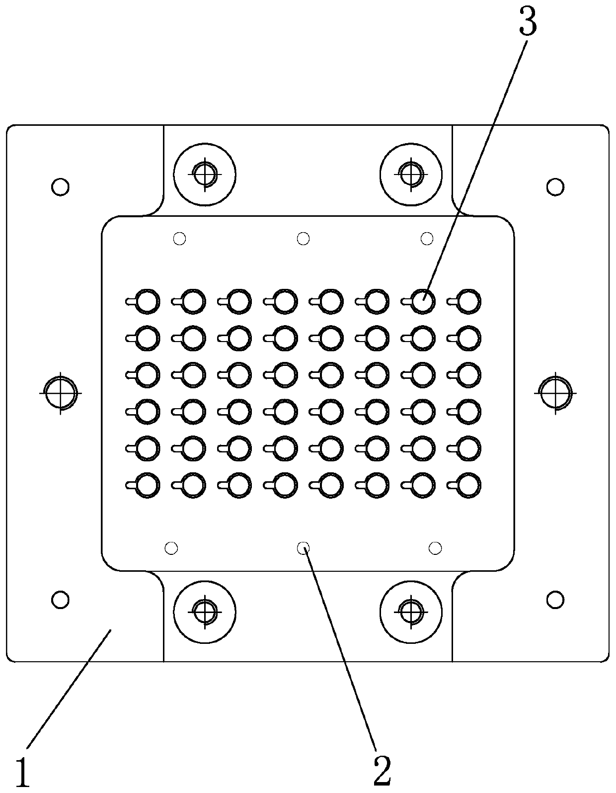
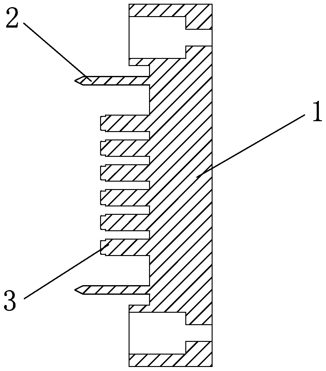
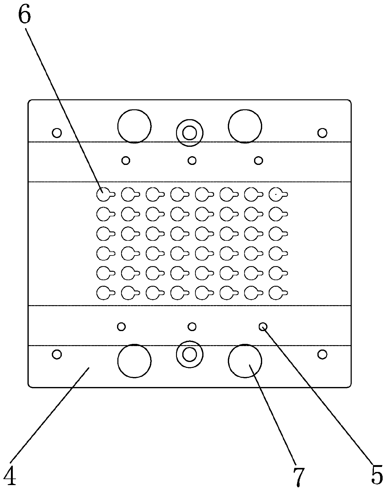
[0028] combine Figure 1 to Figure 4 , the invention discloses a stamping die for a transfer protective film, which includes an upper die and a lower die that cooperate with each other. The upper mold includes an upper mold template 1 , and positioning pins 2 and punching pins 3 arranged on the upper mold template 1 . The punching pins 3 are arranged in an array in the middle of the upper mold template 1 , and the positioning pins 2 are located outside the punching pins 3 . The punching needle 3 has a cylindrical structure, and a boss is provided on the front end of the punching needle 3 to converge inwardly. Preferably, the height of the boss at the front end of the punching pin 3 is less than 2 mm, preferably 0.8-1.3 mm. The positioning pin 2 is a needle body structure with a tapered front end and a cylindrical body; the lower mold includes a lower mold template 4 . A punching hole 6 matched with the punching pin 3 and a positioning hole 5 matched with the positioning pin...


PUM


Abstract

The invention belongs to the field of protective film production equipment and discloses a transfer protective film punching and laminating mold, a punching and laminating machine and a punching and laminating combination method. The punching and laminating mold comprises an upper mold and a lower mold which are matched. The upper mold comprises an upper mold plate, locating pins and punch needles, wherein the locating pins and the punch needles are arranged on the upper mold plate; the punch needles are arrayed in the middle of the upper mold plate. Each punch needle is of a columnar structure. The front end of each punch needle is shrunk inwards in a step mode to form a boss. The front end of each locating pin is in a pointed cone shape, and the main body of each locating pin is of a cylindrical pin body structure. The lower mold comprises a lower mold plate. Punch holes matched with the punch needles and locating holes matched with the locating pins are formed in the lower mold plate. Each punch hole is gradually shrunk from the punching surface to the back surface and is of a conical hole structure. The punching and laminating mold provided by the invention is simple and reasonable in structure, capable of completing the punching and laminating process at a time, high in operating efficiency, high in punching and laminating precision, small in abrasion to the punch needlesand good in using effect and reduces the labor intensity and labor time.

Description

technical field [0001] The invention relates to the field of protective film production equipment, in particular to a transfer protective film stamping die, a stamping machine and a stamping compound method. Background technique [0002] With the advancement of technology and the development of multimedia technology, the application range of camera modules has gradually expanded, and is widely used in digital cameras, digital video recorders, mobile phones, monitors and other electronic products with camera functions. However, the lens in the traditional camera module is exposed to the air during production and use, and the optical performance and mechanical performance will be reduced, which seriously shortens the service life of the camera module. Therefore, the camera module protective film came into being. [0003] Our company uses silica gel instead of foam glue, and makes a protective film by first injecting silica gel and then compounding it. In the production proce...

Claims


Application Information

Patent Timeline
Patent Type & Authority Applications(China)
IPC IPC(8): B26F1/44B26F1/40B26F1/24B26D9/00
CPCB26F1/44B26F1/40B26F1/24B26D9/00
Inventor 胡亨炳
Owner 苏州优派克电子科技有限公司
Why Eureka
Try Eureka