mortar launcher

A technology for launching devices and mortars, which is applied to the field of mortar launching devices, can solve the problems of reduced shooting accuracy, insufficient firing energy, and insufficient sliding speed of shells.

Inactive Publication Date: 2017-10-03
GUANGZHOU INST OF RAILWAY TECH
View PDF4 Cites 0 Cited by
  • Summary
  • Abstract
  • Description
  • Claims
  • Application Information

AI Technical Summary

Problems solved by technology

[0005] The existence of the gap also affects the centering of the shell in the chamber, causing the fired shell to swing when it moves along the barrel, and the amount of gunpowder gas leakage of each shell is inconsistent, resulting in the dispersion of the muzzle velocity, which reduces the shooting accuracy of the shell.
[0006] To sum up, if the gap between the shell and the bore wall is large, the rate of fire of the shell increases, but the initial velocity of the shell decreases and the shooting accuracy decreases; the gap between the shell and the bore wall is small, the initial velocity of the shell increases, and the shooting accuracy improves, but The rate of fire of the mortar is reduced, and it may even cause blind fire due to insufficient firing energy due to the insufficient sliding speed of the shell

Method used


Image

  • mortar launcher
  • mortar launcher
  • mortar launcher

Examples


Embodiment Construction

[0028] Embodiments of the present invention are described in detail below:

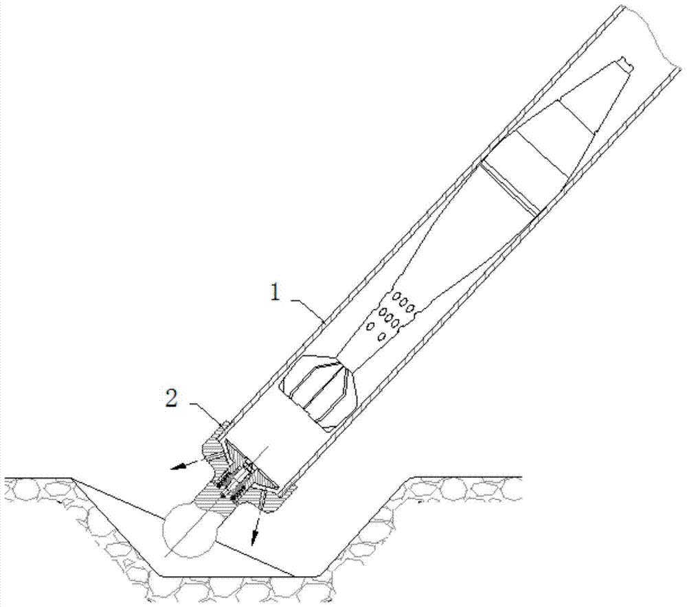
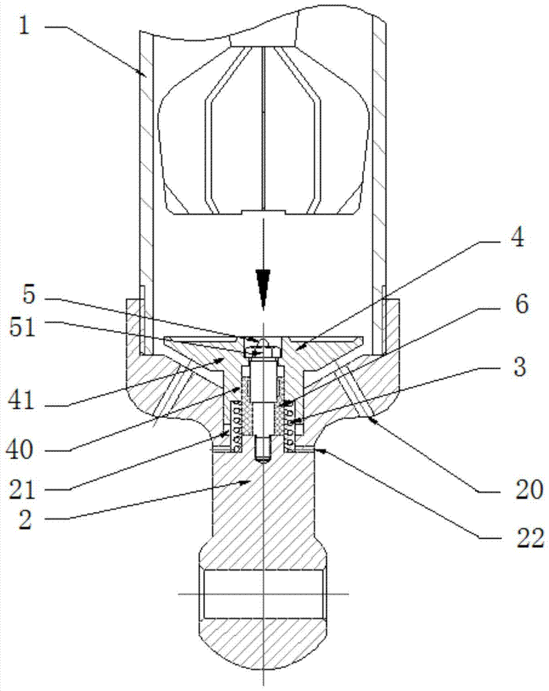
[0029] Such as figure 2 , 3 As shown (the direction of the arrow is the gas discharge direction), the mortar launching device described in the present embodiment includes a breech 2, an elastic member 3, a blocking member 4 and a cylindrical barrel 1 with a bore, and the breech 2 is installed at one end of the barrel 1, and the breech 2 is provided with a firing pin 5 located in the bore, and the blocking member 4 includes a bushing 40 and a shoulder 41 arranged outside the bushing 40. The sleeve 40 is set outside the firing pin 5, the first end of the elastic member 3 abuts on the blocking member 4, and the second end abuts on the breech 2, and the breech 2 is provided with at least one The first exhaust hole 20 (there are two first exhaust holes 20 in this embodiment, and the two first exhaust holes 20 are arranged at the position close to the shoulder), when the elastic member 3 is in the origin...


PUM


Abstract

The invention discloses a mortar launching device, which comprises a breech, an elastic member, a blocking member and a cylindrical barrel with a bore, the breech is installed at one end of the barrel, and the breech is provided with a The firing pin in the gun bore, the blocking member includes a bushing and a shoulder arranged outside the bushing, the bushing is set outside the firing pin, the first end of the elastic member abuts against the blocking member, The second end abuts on the breech, and the breech is provided with at least one first vent hole, and when the elastic member is in the original state, the first vent hole communicates with the gun bore; When compressed, the shoulder blocks the first vent hole. The mortar launching device can adopt a barrel inner diameter with a small gap under the premise of ensuring that the mortar shell can slide down reliably and the air is discharged from the first exhaust hole in the gun tail, so that the initial velocity of the shell can be increased and the shooting range can be increased. , while effectively improving shooting accuracy.

Description

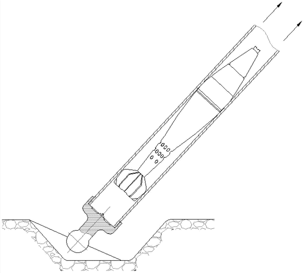
technical field [0001] The invention relates to the technical field of design and manufacture of muzzle loading mortars, in particular to a mortar launching device. Background technique [0002] Such as figure 1 As shown, in the traditional mortar, the shell is loaded from the muzzle, and then the shell slides down the barrel by its own gravity and hits the firing pin at the bottom to fire, and the gas generated by the shell is discharged from the muzzle. In order to allow the compressed gas in the barrel to flow out smoothly when the shell slides down without affecting the downward speed of the shell, there must be a gap between the shell and the wall of the bore, that is to say, the diameter of the shell is smaller than the inner diameter of the barrel, which is the purpose of muzzle loading. A necessary condition for shells. [0003] The air under the shell needs to be discharged upwards from the gap between the shell and the bore wall, so it takes a certain amount of t...

Claims


Application Information

Patent Timeline
Patent Type & Authority Patents(China)
IPC IPC(8): F41F1/06
Inventor 刘丽华
Owner GUANGZHOU INST OF RAILWAY TECH
Why Eureka
Try Eureka