
Curve distribution type shock wave automatic target scoring system

A distributed, shock wave technology, applied in target indication systems, moving targets, targets, etc., can solve the problems of misalignment of calculation centers, increase calculation errors and offsets of target reporting equipment, and improve work reliability and improve The effect of waveform acquisition accuracy

Active Publication Date: 2015-09-23
合肥君信电子科技有限公司
View PDF7 Cites 8 Cited by
  • Summary
  • Abstract
  • Description
  • Claims
  • Application Information

AI Technical Summary

Problems solved by technology

In actual use, since the current target paper laying is manually taken and positioned, there must be many problems such as installation skew and offset, not to mention that some target paper itself will also have some manufacturing errors, so it often leads to the center of the target paper. It does not coincide with the default calculation center of the target reporting equipment, which further increases the calculation error of the aforementioned target reporting equipment

Method used


Image

  • Curve distribution type shock wave automatic target scoring system
  • Curve distribution type shock wave automatic target scoring system
  • Curve distribution type shock wave automatic target scoring system

Examples


Embodiment Construction

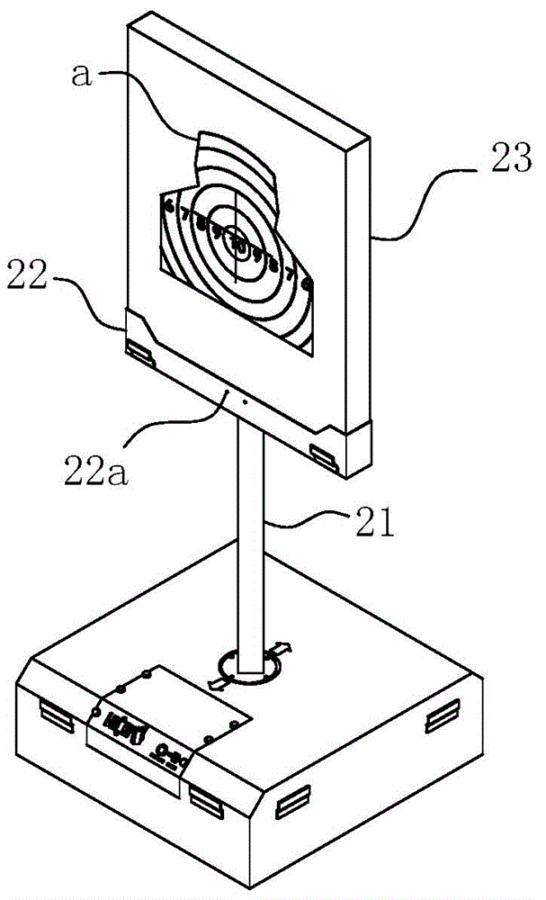
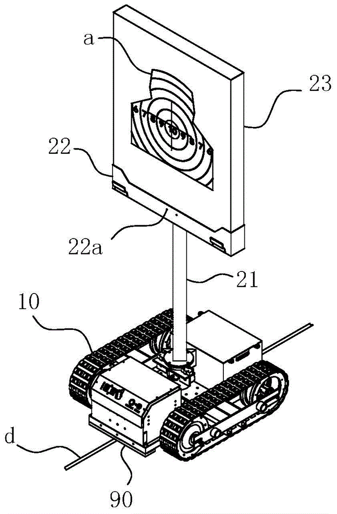
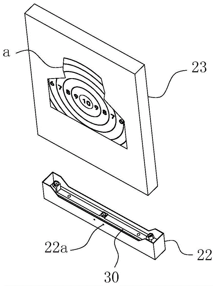
[0061] For ease of understanding, the attached Figure 1-21 Concrete testing device of the present invention and operation process thereof are further described as follows:

[0062] The specific structure of the present invention is as Figure 1-18 As shown, it takes the traveling mechanism 10 and the target frame assembly arranged on the traveling mechanism 10 as the main body, and is matched with a magnetic strip a that can be laid at will or embedded in the ground. The magnetic induction part 90 is also the magnetic sensor, through the control of the information control terminal, so as to realize the self-propelling purpose of the traveling mechanism 10 to find the magnetic track-find the magnetic track-align the magnetic track.

[0063] In order to further enhance the adaptability of the present invention, as Figure 15-18As shown, the present invention is also provided with a rotatable target surface structure at the target frame assembly. It utilizes the rotational co...


PUM


Abstract

The invention relates to the field of automatic target scoring equipment, in particular to a curve distribution type shock wave automatic target scoring system. The curve distribution type shock wave automatic target scoring system comprises a walking mechanism and a target frame assembly; the target frame assembly comprises a target rod, a mounting groove seat and a target plate; a sensor support is arranged in a groove cavity of the mounting groove seat, and sensors are arranged on the sensor support; the sensors are sequentially arranged along the same circumferential line, and the center of the circumference is located in the direction of the induction ends of the sensors; the center of the circumference is located on a connecting line of the middle sensor and the central point of target paper; when the circumferential line formed by the sensors is located on the minimum radius, the center of the circumference is located on the central point of the target paper; the target plate is in a square flat tube shape, and the sensor support is located in a cavity defined by the target plate and the mounting groove seat; and a splinter-proof plate for protecting the sensors is located on the face whether the face of the mounting groove seat is in the shooting direction. The curve distribution type shock wave automatic target scoring system is reasonable and reliable in structure, therefore, the working reliability of the equipment is ensured, and meanwhile, the target scoring precision and the target scoring efficiency are further improved.

Description

technical field [0001] The invention relates to the field of precision shooting automatic target reporting equipment, in particular to a curved distributed shock wave automatic target reporting system. Background technique [0002] Today, with the rapid development of electronic technology, in order to realize the rapid and accurate target reporting function during live ammunition shooting training of light weapons, metal body double / multi-layer on-off technology, laser interruption technology, image recognition technology and even box-type shock wave acoustic target Automatic target reporting equipment based on high-tech technology and other high-tech has been widely used. Among them, shock wave acoustic target equipment is widely used because it uses sound waves to achieve non-contact, long service life and high cost performance. [0003] Most of the existing shock wave acoustic target equipment in China adopts L-shaped or in-line sensor array distribution. Among them, th...

Claims


Application Information

Patent Timeline
IPC IPC(8): F41J5/06F41J7/00F41J1/00F41J1/10
Inventor 陈向春李朋辉秦子刚战延谋
Owner 合肥君信电子科技有限公司
Learn More