Physical quantity sensor, altimeter, electronic apparatus, and moving object
A technology of physical quantity sensor and electronic equipment, which is used in the measurement of fluid pressure, height/level measurement, and measurement of fluid pressure through electromagnetic components, which can solve the problems of inability to detect temperature with high precision, and inability to exert excellent pressure detection accuracy.
- Summary
- Abstract
- Description
- Claims
- Application Information
AI Technical Summary
Problems solved by technology
Method used
Image
Examples
no. 1 approach >
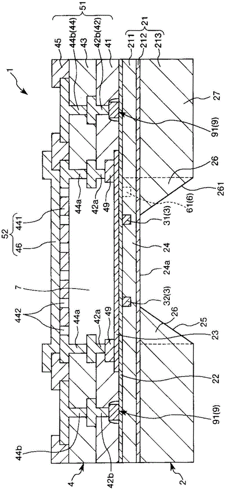
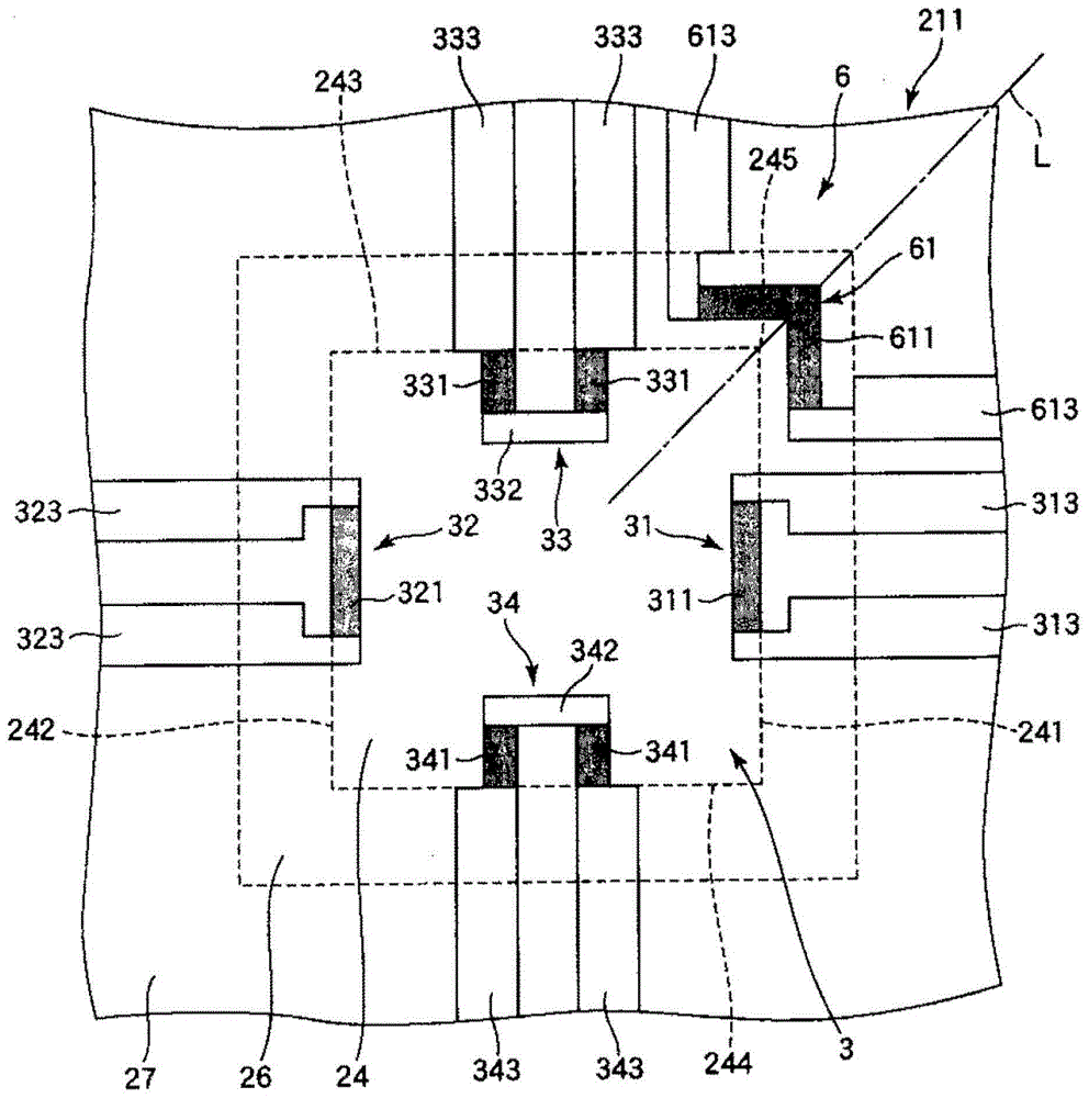
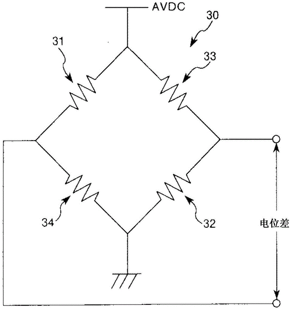
[0073] figure 1 It is a sectional view showing the first embodiment of the physical quantity sensor of the present invention. figure 2 is showing figure 1 The shown physical quantity sensor has a deflection sensor and a top view of a temperature sensor. image 3 yes to contain figure 2 The circuit diagram of the deflection sensor is shown for illustration. Figure 4 ~ Figure 11 are right figure 1 A cross-sectional view illustrating a manufacturing method of the physical quantity sensor shown. Also, in the following description, the figure 1 The upper side in is described as "Up", and the lower side is described as "Down".
[0074] The physical quantity sensor 1 is a pressure sensor capable of detecting pressure. By using the physical quantity sensor 1 as a pressure sensor, for example, it can be mounted on various electronic devices and used for height measurement.
[0075] Such as figure 1 As shown, a physical quantity sensor 1 includes a substrate 2 , a deflection...
no. 2 approach >
[0132] Next, a second embodiment of the physical quantity sensor of the present invention will be described.
[0133] Figure 12 It is a plan view showing the second embodiment of the physical quantity sensor of the present invention. Figure 13 yes to contain Figure 12 The circuit diagram of the temperature sensor is shown for illustration.
[0134] Hereinafter, a second embodiment of the physical quantity sensor of the present invention will be described, focusing on differences from the above-described embodiment, and descriptions of the same matters will be omitted.
[0135] The second embodiment is the same as the above-mentioned first embodiment except that the configuration of the temperature sensor is different.
[0136] Such as Figure 12 As shown, the temperature sensor 6 of this embodiment has four piezoelectric resistance elements (temperature detection elements) 61 , 62 , 63 , and 64 . In addition, these piezoresistive elements 61, 62, 63, and 64 have piezor...
no. 3 approach >
[0143] Next, a third embodiment of the physical quantity sensor of the present invention will be described.
[0144] Figure 14 It is a cross-sectional view showing a third embodiment of the physical quantity sensor of the present invention.
[0145] Hereinafter, a third embodiment of the physical quantity sensor of the present invention will be described, focusing on differences from the above-described embodiment, and descriptions of the same matters will be omitted.
[0146] The third embodiment is the same as the first embodiment described above except that the arrangement of the temperature sensor is different.
[0147] Such as Figure 14 As shown, in the physical quantity sensor 1 of the present embodiment, the piezoresistive element 61 (the piezoresistor portion 611 ) included in the temperature sensor 6 is located outside the cavity 7 in plan view. That is, in a plan view, the diaphragm 24 overlaps the hollow portion 7 , and the piezoresistive element 61 and the hol...
PUM
 Abstract
Description
Claims
Application Information
 - R&D
- Intellectual Property
- Life Sciences
- Materials
- Tech Scout
- Unparalleled Data Quality
- Higher Quality Content
- 60% Fewer Hallucinations
Browse by: Latest US Patents, China's latest patents, Technical Efficacy Thesaurus, Application Domain, Technology Topic, Popular Technical Reports.
© 2025 PatSnap. All rights reserved.Legal|Privacy policy|Modern Slavery Act Transparency Statement|Sitemap|About US| Contact US: help@patsnap.com


