Submerged arc furnace low-pressure filtering energy-saving cabinet with push-pull type reactance handcart

A mobile, handcart-resistant technology, applied to harmonic reduction devices, AC networks to reduce harmonics/ripples, reactive power compensation, etc., can solve problems such as inconvenient maintenance operations, poor heat dissipation, and reduced workload. Achieve the effects of stable and smooth movement, strong service life, and convenient disassembly and assembly

Inactive Publication Date: 2015-09-23
叶选茂
View PDF7 Cites 1 Cited by
  • Summary
  • Abstract
  • Description
  • Claims
  • Application Information

AI Technical Summary

Problems solved by technology

[0002] The submerged arc furnace needs reactive power compensation through capacitive reactance and other components. For example, the invention patent No. 201220313688.5 discloses a reactive power low-voltage compensation cabinet for submerged arc furnaces. There are a large number of capacitors and reactors inside. After the reactor is fixed in the reactive power compensation low-voltage cabinet of the hot furnace, it is inconvenient to disassemble and assemble due to the small space of the cabinet. When a reactor is damaged, the maintenance operation is very inconvenient. If the reactor group can be removed from the cabinet Pulling it out as a whole will greatly reduce the workload; in addition, the existing low-voltage cabinets for reactive power compensation still have problems such as being too bulky and poor in heat dissipation

Method used


Image

  • Submerged arc furnace low-pressure filtering energy-saving cabinet with push-pull type reactance handcart
  • Submerged arc furnace low-pressure filtering energy-saving cabinet with push-pull type reactance handcart
  • Submerged arc furnace low-pressure filtering energy-saving cabinet with push-pull type reactance handcart

Examples


Embodiment Construction

[0022] Below in conjunction with specific embodiment and accompanying drawing, the present invention will be further described:

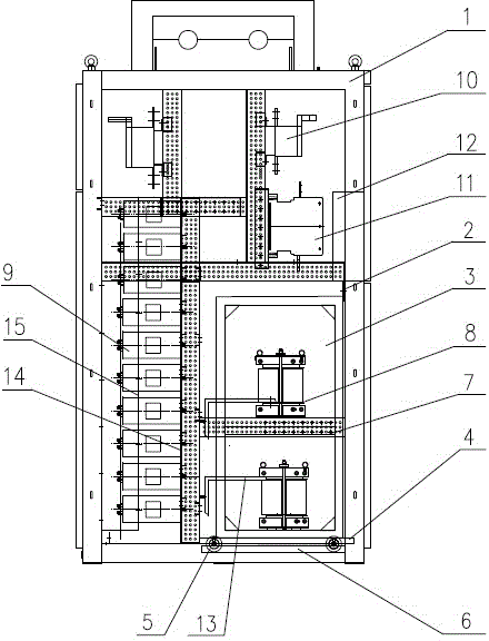
[0023] Refer to attached figure 1 and Figure 7 As shown, the submerged arc furnace low-voltage filter energy-saving cabinet with a push-pull mobile reactance handcart of the present invention includes a cabinet body 1, and a capacitor group 9 and a reactor group 8 are arranged in the cabinet body 1, and each reactor of the reactor group 8 is divided into The first layer is set in the push-pull mobile handcart 3, the reactor group 8 is led to the door-type mobile terminal box 12 through the detachable connection copper bar 13 through the fuse isolator 10 and the vacuum contactor 11, and the push-pull mobile handcart 3. It is movably arranged in the cabinet body 1 through the pulley slide rail mechanism.

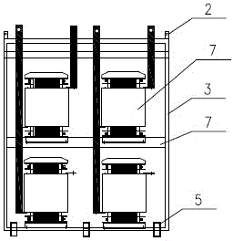
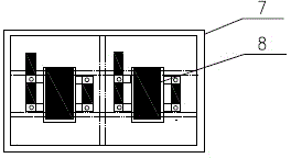
[0024] refer to figure 2 , image 3 As shown, the push-pull mobile handcart 3 includes a hollow frame, and at least two layers of reactor sup...


PUM


Abstract

The invention provides a submerged arc furnace low-pressure filtering energy-saving cabinet with a push-pull type reactance handcart, and the cabinet comprises a cabinet body. The interior of the cabinet is provided with a capacitor bank and a reactor group, wherein all reactors of the reactor group are arranged in the push-pull type reactance handcart in a layered manner. The reactor group is led to a gate-type mobile terminal box through a connection copper bar in detachable connection, a fuse-type isolator and a vacuum contactor. The push-pull type reactance handcart is disposed in the cabinet body in a movable type through a pulley and sliding rail mechanism. The beneficial effects of the invention lie in that the reactor group is integrally disposed in the push-pull type reactance handcart, the disassembly and assembly are convenient, and the workload of maintenance is greatly reduced; a conductive connection structure is reasonable, the routing is clear, the space in the cabinet is used completely, and the heat dissipation effect is guaranteed; the installation structure of capacitors is light and exquisite, and the heat dissipation effect is good; a handcart structure is firm, the service life is long, and the machining cost is low; the sliding rail and pulley structure is simple and convenient, and the movement is stable and smooth.

Description

technical field [0001] The invention relates to the technical field of a low-voltage reactive power compensation cabinet for a submerged arc furnace, and specifically provides a low-voltage filter energy-saving cabinet for a submerged arc furnace with a push-pull movable reactance handcart. Background technique [0002] The submerged arc furnace needs reactive power compensation through capacitive reactance and other components. For example, the invention patent No. 201220313688.5 discloses a reactive power low-voltage compensation cabinet for submerged arc furnaces. There are a large number of capacitors and reactors inside. After the reactor is fixed in the reactive power compensation low-voltage cabinet of the hot furnace, it is inconvenient to disassemble and assemble due to the small space of the cabinet. When a reactor is damaged, the maintenance operation is very inconvenient. If the reactor group can be removed from the cabinet The overall extraction will greatly red...

Claims


Application Information

Patent Timeline
Patent Type & Authority Applications(China)
IPC IPC(8): H02J3/18H02J3/01
CPCY02E40/30Y02E40/40
Inventor 叶选茂
Owner 叶选茂
Why Eureka
Try Eureka