Piston ring for internal combustion engines with increased fatigue strength, and method for producing same

A technology of fatigue resistance and piston ring, applied in the field of piston ring, can solve the problems of piston ring breakage and enlargement

Inactive Publication Date: 2015-09-23
FEDERAL MOGUL BURSCHEID
View PDF9 Cites 4 Cited by
  • Summary
  • Abstract
  • Description
  • Claims
  • Application Information

AI Technical Summary

Problems solved by technology

These tiny cracks grow in size over time, eventually causing the piston rings to break

Method used


Image

  • Piston ring for internal combustion engines with increased fatigue strength, and method for producing same
  • Piston ring for internal combustion engines with increased fatigue strength, and method for producing same
  • Piston ring for internal combustion engines with increased fatigue strength, and method for producing same

Examples


Embodiment Construction

[0036] The same reference numerals in the drawings and description indicate the same or similar elements.

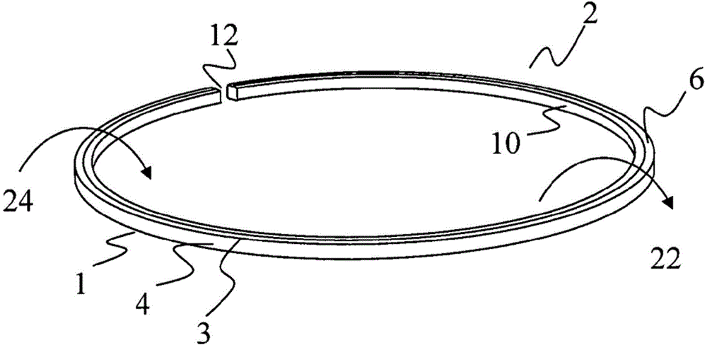
[0037] figure 1 A perspective view of the piston ring 2 is shown. The piston ring 2 has a working surface 4 located on the outside. The underside of the piston ring, which cannot be seen in this figure, forms the underside of the piston ring 2, whose reference number is 8 in other figures. The upper side of the piston ring is formed by the upper side 6 of the piston ring. The working surface 4 is in contact with the upper side 6 of the piston ring at the upper edge 3 of the working surface 4. The working surface 4 is in contact with the lower side of the piston ring at the lower edge 1 of the working surface 4, and the reference number of the lower side of the piston ring is 8, which is not shown in the figure. The piston ring is bounded on the inside by the inner surface 10 of the piston ring. The piston ring 2 opens at the piston ring gap 12.

[0038] Under load, the p...


PUM

PropertyMeasurementUnit
thicknessaaaaaaaaaa

Abstract

The present invention relates to a piston ring (2) with increased fatigue strength, made of a plastically deformable material. The piston ring (2) has a bearing surface (4) which is limited at the top by an upper bearing surface edge (3) and at the bottom by a lower bearing surface edge (1). Along at least one part of the circumference, compressive stresses are introduced to the upper bearing surface edge (3) and / or to the lower bearing surface edge (1), wherein said compressive stresses are produced by rolling.

Description

Technical field [0001] The invention relates to a piston ring and a method of manufacturing such a piston ring. The piston ring includes a plastically deformable material and has at least one edge located between the working surface and the side surface of the piston ring, and compressive stress is introduced to the edge between the working surface and the side surface of the piston ring through rolling. Background technique [0002] Existing piston rings tend to break under load. The piston ring loads heat and power when the engine is running. In particular, the high combustion pressure, together with the axial groove, causes the piston ring to twist into the piston ring groove of the piston. The maximum stress is generated at the upper or lower working edge of the piston ring, opposite to the piston ring gap (located at 180°) of the piston ring. If the stress becomes too large, one or more micro cracks or initial cracks are generated in the boundary area. These tiny cracks ...

Claims


Application Information

Patent Timeline
Patent Type & Authority Applications(China)
IPC IPC(8): F16J15/56F15B15/14F16J9/26
CPCB23P9/02F16J9/20F16J9/26B23P15/06Y10T29/49281F02F5/00F16J15/56F16J9/02F16J9/203F16J9/22
Inventor 奈杰尔·格雷斯蒂芬·马克莱纳
Owner FEDERAL MOGUL BURSCHEID
Why Eureka
Try Eureka