Injection mold for faucet shell

A faucet shell and injection mold technology, applied in the field of mold equipment, can solve the problems of low processing precision and inability to form at one time, and achieve the effects of high processing precision, convenient operation and stable structure

Inactive Publication Date: 2015-09-30
WUXI YICHEN MOLD TECH
View PDF1 Cites 1 Cited by
  • Summary
  • Abstract
  • Description
  • Claims
  • Application Information

AI Technical Summary

Problems solved by technology

[0008] At present, the existing injection molds for faucet shell processing cannot be formed at one time when in use, and the processing accuracy is low

Method used


Image

  • Injection mold for faucet shell
  • Injection mold for faucet shell

Examples


Embodiment Construction

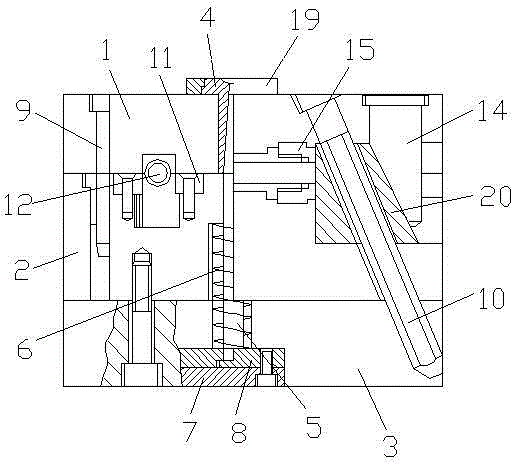
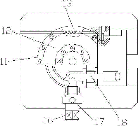
[0025] refer to figure 1 with figure 2 As shown, an injection mold for a faucet housing includes a fixed template 1, a movable template 2, a mold foot 3 and a sprue sleeve 4, and the fixed template 1, the movable template 2 and the mold foot 3 are sequentially arranged from top to bottom, and the The sprue bushing 4 is arranged in the middle of the fixed formwork 1, a pulling rod 5 is arranged under the sprue bushing 4, a spring 6 is arranged outside the pulling rod 5, and a rear top plate 7 and a rear top plate 7 are arranged in the middle of the mold foot 3 The front top plate 8, the pull rod 5 is arranged on the rear top plate 7, the two sides of the sprue sleeve 4 are respectively provided with a guide post 9 and an inclined guide post 10, and one side of the guide post 9 is provided with an arc-shaped pressure plate 11 , the arc-shaped pressing plate 11 is provided with a gear shaft 12, and the outer side of the pinion shaft 12 is provided with a rack 13, the rack 13 is...


PUM


Abstract

The invention discloses an injection mold for a faucet shell. The injection mold for the faucet shell comprises a fixed mold plate, a movable mold plate, a mold leg and a sprue bush. The fixed mold plate, the movable mold plate and the mold leg are arranged from top to bottom in sequence, the sprue bush is arranged in the middle of the fixed mold plate, a pulling rod is arranged below the sprue bush, a spring is arranged on the outer side of the pulling rod, a rear top plate and a front top plate are arranged in the middle of the mold leg, the pulling rod is arranged on the rear top plate, a guide column and an oblique guide column are arranged on the two sides of the sprue bush respectively, an arc-shaped pressing plate is arranged on one side of the guide column, a gear shaft is arranged on the arc-shaped pressing plate, a rack is arranged on the outer side of the gear shaft, the rack is meshed with the gear shaft, the gear shaft is fixedly connected with the arc-shaped pressing plate, and a sliding block is arranged on the outer side of the oblique guide column. The injection mold for the faucet shell is convenient to machine, the faucet shell can be formed at a time, accurate demolding can be kept, and machining precision is high.

Description

technical field [0001] The invention relates to the technical field of mold equipment, in particular to an injection mold for a faucet shell. Background technique [0002] The processing enterprise should first equip each pair of molds with a resume card to record and count its use, care (lubrication, cleaning, anti-rust) and damage in detail. Based on this, it can be found which parts and components are damaged and the degree of wear, so as to provide And the information materials to solve the problem, as well as the molding process parameters of the mold and the materials used in the product, so as to shorten the trial run time of the mold and improve the production efficiency. [0003] The processing enterprise should test the various properties of the mold under the normal operation of the injection molding machine and the mold, and measure the size of the final molded plastic part. Through this information, the current state of the mold can be determined, and the ca...

Claims


Application Information

Patent Timeline
Patent Type & Authority Applications(China)
IPC IPC(8): B29C45/33B29C45/40
CPCB29C45/262B29C45/33B29C45/40
Inventor 钱根来李康魏鑫夏守忠陈微霞丁亭
Owner WUXI YICHEN MOLD TECH
Why Eureka
Try Eureka