
A narrow-flange steel column expanded airfoil column foot and its construction technology

A construction technology and steel column technology, applied in basic structure engineering, construction, etc., can solve the problems of too large, uneconomical, and too deep caps, achieve good economic benefits, improve integrity, and reduce the depth of embedding. Effect

Active Publication Date: 2016-11-23
黄冀卓 +1
View PDF6 Cites 0 Cited by
  • Summary
  • Abstract
  • Description
  • Claims
  • Application Information

AI Technical Summary

Problems solved by technology

The current domestic codes are conservative in the design of the embedding depth of column feet. Except for building structures with basements, they all face the problem that the foundation, foundation beams, caps, etc. are too large and too deep due to the excessive embedding depth of steel column feet. Uneconomical problems

Method used


Image

  • A narrow-flange steel column expanded airfoil column foot and its construction technology
  • A narrow-flange steel column expanded airfoil column foot and its construction technology
  • A narrow-flange steel column expanded airfoil column foot and its construction technology

Examples


Embodiment 1

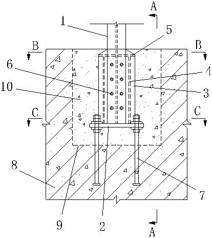
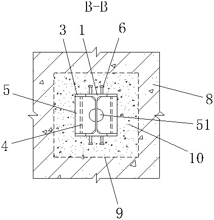
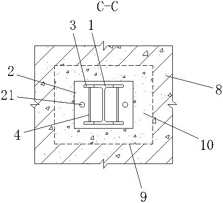
[0024] Embodiment one: if Figure 1~4 As shown, a narrow-flange steel column expanded airfoil column foot, the column foot is embedded in the reinforced concrete foundation, including the base plate 2 arranged on the bottom end surface of the H-shaped steel column 1, and two flanges respectively arranged on the two flanges of the steel column. The wing expansion plate 3 of the side wall, the wing expansion plate 3 is welded on the side wall of the flange through the groove full penetration weld, and is welded with the bottom plate 2, and the vertical expansion plate is welded between the two opposite wing expansion plates. Straight stiffener 4, the vertical stiffener 4 is parallel to the web of the steel column, and the flange, web, wing expansion plate 3, vertical stiffener 4 and the bottom plate together form a cavity, the cavity A horizontal stiffener 5 is provided at the top opening of the chamber, several pegs 6 are evenly distributed on the bottom of the outer walls of t...


PUM


Abstract

The invention relates to a flange extension type column foot for a narrow flange steel column, and a construction technology of the column foot. The column foot is characterized in that the column foot is embedded into a reinforced concrete foundation; the column foot comprises a bottom plate arranged at the bottom end face of the steel column, and flange extension plates arranged on two side walls of two flanges of the steel column respectively; the flange extension plates are welded on the side walls of the flanges by groove complete-penetration welds, and welded with the bottom plate; vertical stiffening ribs are welded between the two opposite flange extension plates; horizontal stiffening ribs are arranged at a top port of a containing cavity; a plurality of studs are uniformly on the bottoms of outer wall surfaces of the two flanges respectively; and anchor bolts are arranged at the two ends of the bottom plate. According to the column foot, with the adoption of the horizontal stiffening ribs and the vertical stiffening ribs, the effective bearing width of an embedded part of the steel column is increased, a bending moment and a shearing force borne by an imbedded column foot node can be transferred conveniently, the embedded depth of the steel column can be reduced significantly, and the embedded depth of the foundation or a bearing platform can be further reduced. The column foot has better economic benefits in engineering practices.

Description

technical field [0001] The invention relates to a column base of a narrow flange steel column with expanded airfoil and its construction technology. Background technique [0002] The embedded column foot is to embed the steel column directly into the column foot of the reinforced concrete foundation, foundation beam, and cap. , The concrete of the platform. This method is beneficial to ensure the overall rigidity of the steel column foot and foundation, foundation beam and cap. For the embedded column foot, the most important factor affecting the bending stiffness, bearing capacity and deformation capacity of the column foot is the embedding depth of the steel column. The current domestic codes are conservative in the design of the embedding depth of column feet. Except for building structures with basements, they all face the problem that the foundation, foundation beams, caps, etc. are too large and too deep due to the excessive embedding depth of steel column feet. une...

Claims


Application Information

Patent Timeline
Patent Type & Authority Patents(China)
IPC IPC(8): E02D27/42
Inventor 黄冀卓黄沿才林潮
Owner 黄冀卓
Learn More