soil ripper for plowing

A ripper and soil-touching technology, which is applied to earth movers/shovels, mechanically driven excavators/dredgers, construction, etc., can solve the problems of reduced operating efficiency, tooth tip stress concentration, and low operating efficiency. Achieve the effects of prolonging life, dispersing soil pressure, and reducing soil contact area

Inactive Publication Date: 2017-10-24
HENAN UNIV OF SCI & TECH
View PDF4 Cites 0 Cited by
  • Summary
  • Abstract
  • Description
  • Claims
  • Application Information

AI Technical Summary

Problems solved by technology

Existing rippers are mainly composed of guard plates, tooth tips and corners fixedly connected, wherein the tooth tips and guard plates are in direct contact with the soil and are elements for cracking soil, but the known design of tooth tips and guard plates does not Failure to fully consider the soil-contacting surface characteristics of the tip of the tooth and the guard plate may easily cause the following problems: 1. When the ripper operates, the tip of the tooth is subject to concentrated stress, serious wear and tear, and is often replaced; 2. During the operation, the traditional circular arc The stress concentration of the guard plate on the soil, the soil is compacted, the resistance increases, and the operating efficiency decreases; 3. The clay problem is serious and the operating efficiency is low

Method used


Image

  • soil ripper for plowing
  • soil ripper for plowing
  • soil ripper for plowing

Examples


Embodiment Construction

[0014] The ripper for plowing land of the present invention will be further described in conjunction with specific examples below, so that those skilled in the art can better understand the present invention and implement it, but the examples given are not intended to limit the present invention.

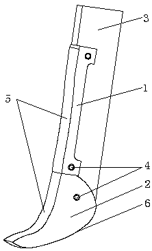
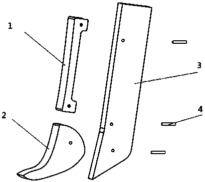
[0015] A ripper for plowing land, such as figure 1 As shown, it includes guard plate 1, tooth tip 2, support angle 3 and fixing pin 4. The tooth tip 2 is installed on the lower end of the support angle 3 through the fixing pin and constitutes the end of the soil, and the described guard plate 1 is fixed through the fixing pin Installed on the upper surface of the middle part of the contact surface of the support angle 3, the upper surface of the guard plate 1 and the tooth tip 2 together constitute the soil contact surface of the ripper, and the soil contact surface of the ripper is composed of the upper surface of the guard plate 1 and the upper and lower surfaces of the tooth tip 2...


PUM


Abstract

A scarifier for soil tillage and preparation comprises a protecting plate, a prong, a support part and fixing pins, wherein the protecting plate and the upper surface of the prone jointly form a scarifier soil-contact curve surface, the upper surface of the protecting plate is in arc connection with the upper surface and the lower surface of the prone to form soil-contact curve surfaces, the upper surface of the prone is the inner soil-contact curve surface, the lower surface of the prong is the outer soil-contact curve surface, the contour curve of the inner soil-contact curve conforms to the equation y=0.0012x<4>-0.0538x<3>+0.8437x<2>-5.8982x+0.0065, and the value range of x is 0-13; the contour curve of the outer soil-contact curve surface conforms to the equation y=0.0002x<4>-0.0013x<3>+0.0074x<2>-0.3443x-16.8925, and the value range of x is -10-13. When the scarifier is used, the motion states of soil when contacting with the soil-contact curve surfaces can be changed, and adhesion and resistance reduction is achieved.

Description

technical field [0001] The invention relates to the technical field of soil tillage, in particular to a ripper for tillage. Background technique [0002] The ripper is a major accessory device of the crawler bulldozer, which is usually hung on the suspension at the rear of the bulldozer and is mainly used for pre-loosening operations on the working face. For bulldozers, rippers can not only be used for loosening soil layers such as clay and hardened permafrost, but also can be used for stripping hard working surfaces such as rocks, hardened salt mines, and rocks with well-developed bedding. It becomes an important working device. Existing rippers are mainly composed of guard plates, tooth tips and corners fixedly connected, wherein the tooth tips and guard plates are in direct contact with the soil and are elements for cracking soil, but the known design of tooth tips and guard plates does not Failure to fully consider the soil-contacting surface characteristics of the tip...

Claims


Application Information

Patent Timeline
Patent Type & Authority Patents(China)
IPC IPC(8): E02F5/32E02F3/76
Inventor 郭志军望红浩岳东东李涛康翔宇王永巍陈毅超谢宁杨亚峰
Owner HENAN UNIV OF SCI & TECH
Why Eureka
Try Eureka