Non-tracking solar compound paraboloid condenser

A compound paraboloid and concentrator technology, applied in the field of solar energy applications, can solve the problems of slow commercialization, poor concentrating effect, and poor availability, and achieve good heat utilization effect, simple generation method, and low application cost.

Inactive Publication Date: 2015-09-30
赵石林
View PDF6 Cites 6 Cited by
  • Summary
  • Abstract
  • Description
  • Claims
  • Application Information

AI Technical Summary

Problems solved by technology

However, by adopting such a light concentrator, although the structure of the light concentrator will be simplified, the precision requirement of light concentration and the manufacturing cost will be reduced, but

Method used


Image

  • Non-tracking solar compound paraboloid condenser
  • Non-tracking solar compound paraboloid condenser
  • Non-tracking solar compound paraboloid condenser

Examples


Embodiment 1

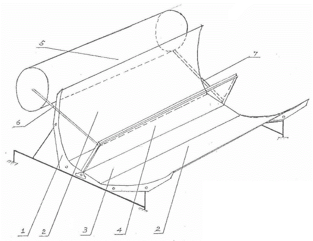
[0032] Application requirements: first, it is completely fixed and free from tracking, second, it is placed on a flat roof, and third, the application site is 30.0 degrees north latitude, and it requires integrated installation with the roof.

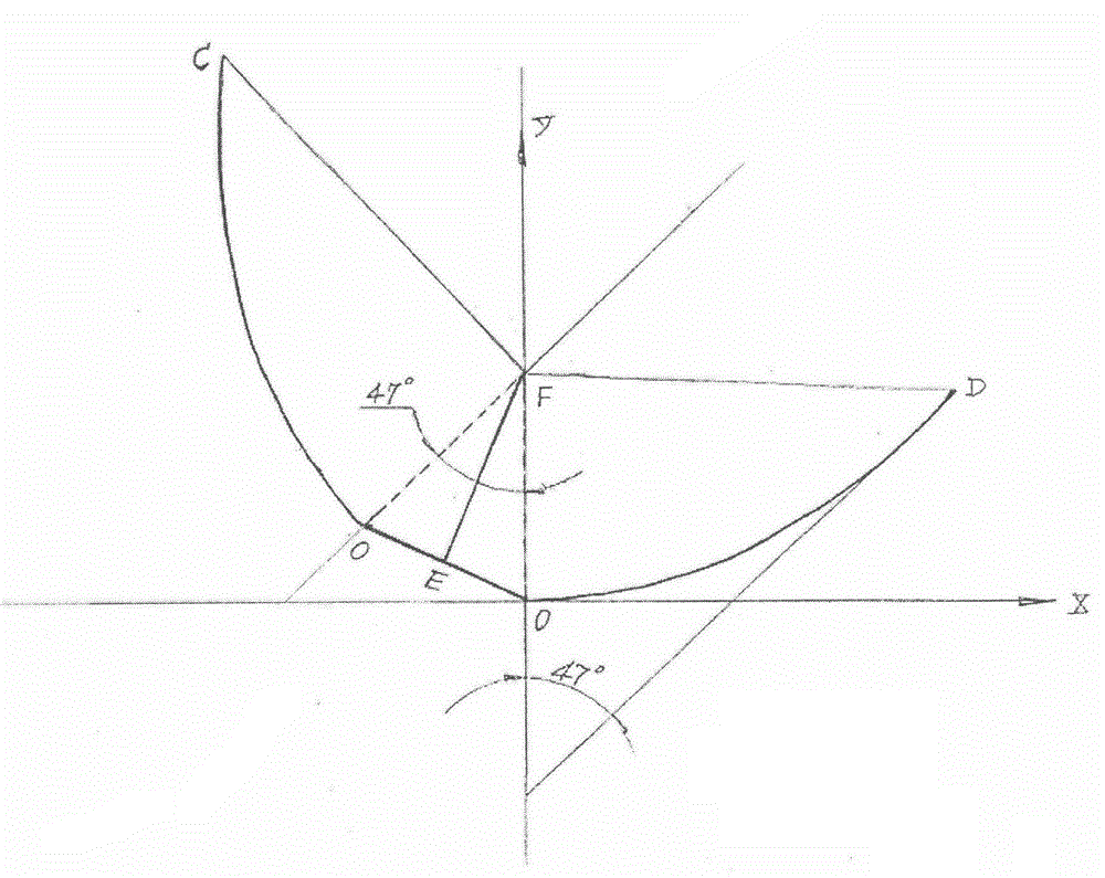
[0033] see figure 1 , 2 , 3 a kind of tracking-free solar compound parabolic concentrator, its compound parabolic mirror surface is compounded and generated by the parabolic light-concentrating curve, according to Y=X2 / 4F parabolic equation, make the parabolic curve coordinate figure that is 50cm with the focal length, in the parabolic curve On the coordinate diagram, according to the fact that the tracking-free solar compound parabolic concentrator is completely fixed as a fixed point, the intercepted half parabola segment located in the 1 image area is rotated clockwise until the angle between its focal line and the Y axis is equal to 47° , move the generated composite parabolic concentrating curve section along the vertical directi...

Embodiment 2

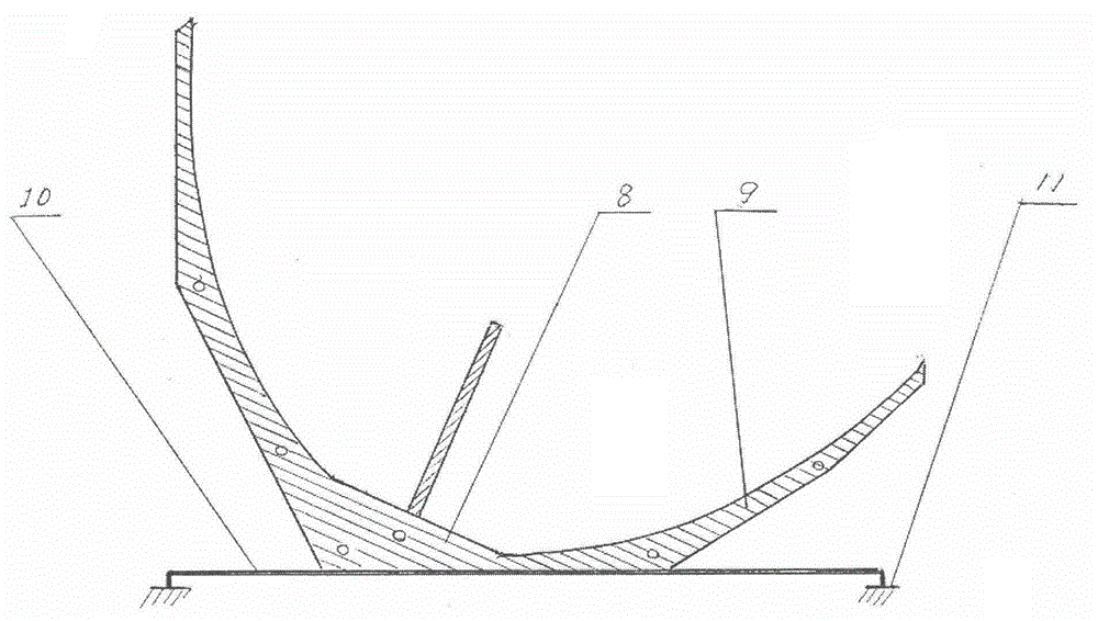
[0035] Application requirements: First, it is completely fixed and free from tracking. The second is that the placement site is a sunny slope roof with a slope of 40°. The third is that the application site is 30° north latitude, and the fourth is that in order not to affect the architectural landscape, the thickness of the generated concentrator shall not exceed 20cm. Under the condition of being completely fixed and tracking-free, it is guaranteed to receive incident sunlight throughout the year.

[0036] see Figure 4 A kind of tracking-free solar compound parabolic concentrator, its compound parabolic reflector surface is generated by compounding the parabolic concentration curve, the generation method is: according to Y=X2 / 4F parabolic equation, make the parabolic curve coordinate map that is 7cm with focal length, in On the parabolic curve coordinate diagram, according to the requirement that the tracking-free solar compound parabolic concentrator is completely fixed, t...


PUM


Abstract

The invention provides a non-tracking solar compound paraboloid condenser which comprises a compound paraboloid condenser mirror support, a paraboloid reflection mirror surface support, a plane reflection mirror surface support, paraboloid reflection mirror surfaces, a plane reflection mirror surface, a heat collector, a heat storage tank, a heat diversion tube, a return tube and a horizontal support frame. A conpound paraboloid reflection mirror surface is formed by combining paraboloid condensation curves; according to different non-tracking requirements, two different cutoff points which correspond to total reflection critical angles are selected on a parabolic curve graph and intercepted, a focal point F serves as a fixed point, and a half parabolic segment located in the first quadrant is rotated in the clockwise direction to make an inclined angle between the focal line of the half parabolic segment and the Y axis be equal to 47 degrees; accordingly, the maximum effective daylighting and concentration ratio of the generated non-tracking solar compound paraboloid condenser can reach four times under all fixed conditions; if adjustment is conducted once every year, the maximum effective daylighting and concentration ratio can reach eight times, and if the adjustment is conducted once every month, the maximum effective daylighting and concentration ratio can reach 20 times.

Description

technical field [0001] The invention relates to the application field of solar energy, in particular to a compound parabolic concentrator of non-light image and tracking-free solar energy. Background technique [0002] Solar energy is the most abundant renewable energy on the earth. Due to its low density and being affected by the sun's altitude angle, azimuth angle, and weather, the utilization rate of solar energy is very low. In order to improve the availability of solar energy, people use solar concentrators to increase solar radiation density. There are mainly types of concentrators such as refraction, reflection, and mixing. Only the tracking system, focusing surface, tracking bracket and transmission machinery can ensure the effective tracking and focusing. Therefore, the manufacturing cost of fully automatic tracking solar concentrators is high, and the operating cost is much higher than that of conventional energy sources, thus hindering its commercial development...

Claims


Application Information

Patent Timeline
IPC IPC(8): F24J2/12F24J2/16F24J2/34F24J2/46F24S23/71F24S23/77
CPCY02E10/40
Inventor 赵石林钱笑语
Owner 赵石林
Why Eureka
Try Eureka