System and method for calibrating optical axis of non-spherical reflecting mirror

A mirror and aspheric surface technology, which is applied in the field of optical assembly and inspection, can solve the problems of increasing the difficulty of the optical axis, and achieve the effect of reducing the risk of mirror surface scratches

Inactive Publication Date: 2015-09-30
XI'AN INST OF OPTICS & FINE MECHANICS - CHINESE ACAD OF SCI
View PDF8 Cites 13 Cited by
  • Summary
  • Abstract
  • Description
  • Claims
  • Application Information

AI Technical Summary

Problems solved by technology

In the current application of aspheric mirrors, there is often a hole in the middle of the mirror, which greatly increases the difficulty of determining its optical axis. How to accurately calibrate the optical axis of aspheric mirrors has become an unavoidable engineering problem.

Method used


Image

  • System and method for calibrating optical axis of non-spherical reflecting mirror
  • System and method for calibrating optical axis of non-spherical reflecting mirror
  • System and method for calibrating optical axis of non-spherical reflecting mirror

Examples


Embodiment Construction

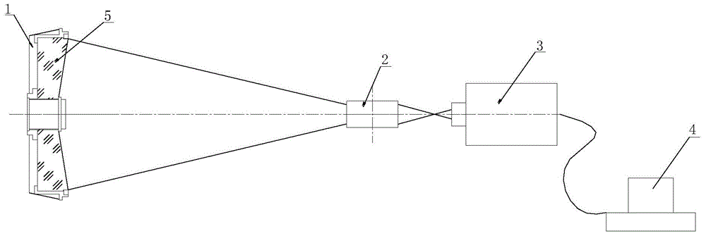
[0030] A system for calibrating the optical axis of an aspheric mirror, including the first optical path, the second optical path and the third optical path, such as Figure 1-5 As shown, the first optical path includes a frame 1, a compensator 2, a laser interferometer 3 and a PC 4 placed in sequence, an aspheric reflector 5 is fixed on the frame 1, and the aspheric reflector, compensator, and laser interferometer The optical axis is coaxial, one end of the laser interferometer is the lens and faces the aspheric reflector, the other end of the laser interferometer is connected to the PC, the lens is a spherical standard lens and matches the R / D value of the aspheric reflector, where R is the radius of the aspheric mirror, D is the diameter of the aspheric mirror;

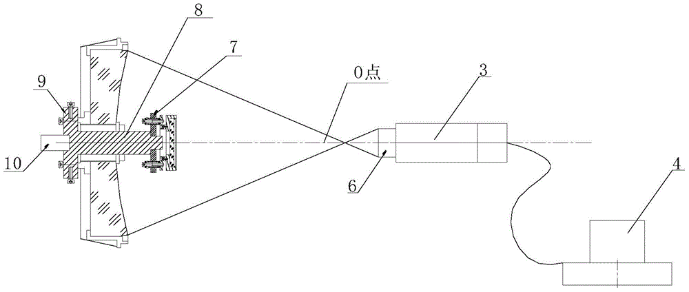
[0031] The structure of the second optical path is: remove the compensator in the first optical path, replace the lens of the laser interferometer 3 in the first optical path with a flat standard lens, install and ...


PUM


Abstract

The invention relates to a system and a method for calibrating an optical axis of a non-spherical reflecting mirror. The system comprises a first optical path, a second optical path and a third optical path, wherein the first optical path comprises a frame I, a compensator, a laser interferometer I and a PC (personal computer) which are sequentially arranged; the second optical path is characterized in that the compensator in the first optical path is removed, a lens of the laser interferometer I in the first optical path is replaced with a flat standard lens, and an adjustment system is mounted and fixed on a frame II through a mesopore of the non-spherical reflecting mirror; the third optical path is structurally characterized in that a posture adjusting tool in the second optical path is fixedly connected with a lathe rotating shaft, and the laser interferometer II in the second optical path is replaced with an internal focusing telescope. According to the system and the method, the optical axis of the non-spherical reflecting mirror is accurately found out in an optical non-contact manner, and a traditional method for determining the optical axis of the non-spherical reflecting mirror through meter running is abandoned.

Description

technical field [0001] The invention belongs to the field of optical assembly and detection, and in particular relates to a method and a system for determining an optical axis of an aspheric reflector. Background technique [0002] The spherical reflector has an infinite number of optical axes, and all the optical axes pass through the spherical center of the spherical reflector. The aspheric reflector has only one optical axis, and it is rotationally symmetrical with respect to the optical axis, that is, the optical axis of the aspheric reflector is its symmetry axis and the approximate spherical center of the aspheric reflector also falls on this optical axis. [0003] Determining the optical axis of the aspheric mirror is of great significance to the assembly, debugging and inspection of the optical system. In the current application of aspheric mirrors, there is often a hole in the middle of the mirror surface, which greatly increases the difficulty of determining its o...

Claims


Application Information

Patent Timeline
Patent Type & Authority Applications(China)
IPC IPC(8): G02B7/198
CPCG02B7/198
Inventor 付兴李智勇耿波张建
Owner XI'AN INST OF OPTICS & FINE MECHANICS - CHINESE ACAD OF SCI
Why Eureka
Try Eureka