Communication electric device and antenna device

A technology for antenna devices and electronic equipment, which is applied in the field of communication, and can solve the problems of small communication electronic equipment, small space for antenna devices, and reduced radiation efficiency of antenna devices, etc.

Inactive Publication Date: 2015-09-30
LENOVO (BEIJING) CO LTD
View PDF2 Cites 11 Cited by
  • Summary
  • Abstract
  • Description
  • Claims
  • Application Information

AI Technical Summary

Problems solved by technology

[0004] In recent years, with the continuous development of wireless communication technology, the functions of communication electronic equipment have become more and more powerful, such as smart phones, smart watches, etc., and the integration has become higher and higher, resulting in smaller and smaller volumes of communication electronic equipment. The space of the antenna device is getting smaller and smaller, resulting in a gradual decrease in the radiation efficiency of the antenna device

Method used


Image

  • Communication electric device and antenna device
  • Communication electric device and antenna device

Examples


Embodiment 1

[0036] Based on the above research, this embodiment provides an antenna device, which includes:

[0037] An antenna unit for sending and receiving wireless signals;

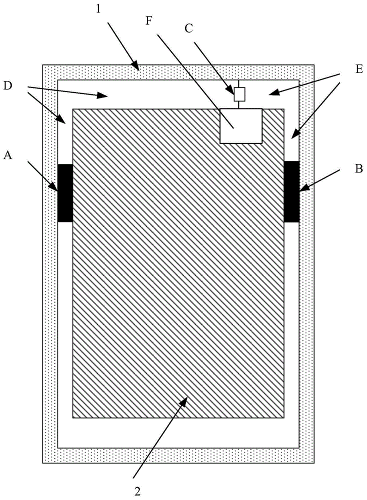
[0038] The first metal part and the second metal part arranged oppositely;

[0039] Wherein, there is a radiation gap between the first metal part and the second metal part, and the feed point of the antenna unit is set in the gap.

[0040] The antenna device can be used in mobile phones, tablet computers, smart watches with wireless communication functions and smart glasses with wireless communication functions.

[0041] The feed point is set at a set position in the extending direction of the slit length, and the slit can be divided into a set length by adjusting the position of the feed point in the slit and using the feed point as a dividing point. The radiation gap in the high frequency band and the radiation gap in the low frequency band.

[0042] The antenna unit may be a dipole antenna structure, or an...

Embodiment 2

[0045] Based on the above-mentioned embodiments, the embodiment of the present application provides another antenna device. In this embodiment, the metal ring of the electronic device is used as the first metal part, and the control circuit board of the electronic device is used as the PCB board or the A metal reinforcing plate of an electronic device is used as the second metal part.

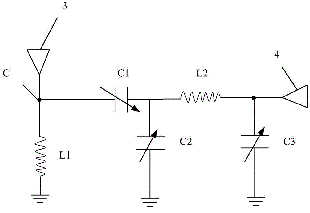
[0046] In order to increase the radiation efficiency and bandwidth of the antenna device, the antenna device includes: a matching circuit connecting the feed point and the first metal part, and the matching circuit is used to make the impedance of the feed point and the first metal part The impedance of the metal parts achieves impedance matching.

[0047] In this embodiment, the metal ring is used as the first metal part of the antenna device, and the PCB or metal reinforcing plate is used as the second metal part of the antenna device, so that the radiation efficiency of the antenna device ca...

Embodiment 3

[0049] Based on Embodiment 1, the embodiment of the present application provides another antenna device. In this embodiment, the metal ring of the electronic device is used as the second metal part, and the PCB board of the control circuit board of the electronic device or the A metal reinforcing plate of an electronic device is used as the first metal component.

[0050] In order to increase the radiation efficiency and bandwidth of the antenna device, the antenna device includes: a matching circuit connecting the feed point and the second metal part, and the matching circuit is used to make the impedance of the feed point and the second metal part The impedance of the metal parts achieves impedance matching.

[0051] In this embodiment, the metal ring is used as the second metal part of the antenna device, and the PCB or metal reinforcing plate is used as the first metal part of the antenna device, so that the radiation efficiency of the antenna device can be improved withou...


PUM


Abstract

The invention discloses a communication electric device and an antenna device. The antenna device includes an antenna unit used for transceiving wireless signals; and a first metal component and a second metal component arranged oppositely, wherein a radiation gap is arranged between the first metal component and the second metal component; and feed points of the antenna unit are arranged in the gap. The antenna device adopts the radiation gap between the first metal component and the second metal component as a radiation body of the antenna, so that the radiation efficiency of the antenna device is improved. The first metal component and the second metal component can be metal structures of the communication electric device and no external component structures are needed to add. Therefore, the radiation efficiency of the antenna device is improved without increasing space occupancy.

Description

technical field [0001] The present invention relates to the technical field of communication, more specifically, to a communication electronic device and an antenna device thereof. Background technique [0002] This section is intended to provide a background or context to the implementations of the application that are recited in the claims. The descriptions herein may include concepts that could be explored, but not necessarily concepts that have been previously thought of or explored. Therefore, unless otherwise indicated herein, what is described in this section is not prior art to the description and claims in this application and is not admitted to be prior art by inclusion in this section. [0003] The radio frequency signal power output by the radio transmitter is sent to the antenna through the feeder, and is radiated by the antenna device in the form of electromagnetic waves. After the electromagnetic wave reaches the receiving location, it is followed by the ant...

Claims


Application Information

Patent Timeline
Patent Type & Authority Applications(China)
IPC IPC(8): H01Q1/44H01Q13/10
Inventor 林规崔斌
Owner LENOVO (BEIJING) CO LTD
Why Eureka
Try Eureka