
Plasma electrode device and method for manufacturing the same

An electrode device and plasma technology, applied in the directions of plasma, separation method, electrode structure, etc., can solve the problems of insufficient ion amount, large amount of ozone generation, inability to effectively remove pollutants, etc., and achieve the effect of reducing the amount of ozone

Active Publication Date: 2015-09-30
LG ELECTRONICS INC
View PDF11 Cites 4 Cited by
  • Summary
  • Abstract
  • Description
  • Claims
  • Application Information

AI Technical Summary

Problems solved by technology

However, the conventional plasma electrode device has the problem that it is difficult to apply the above-mentioned coating with a uniform thickness, and unevenness beyond the allowable range occurs on the surface of the electrode during the coating process.
[0009] In addition, in the case of conventional plasma electrode devices, the amount of generated ions is insufficient, and there is a problem that pollutants cannot be effectively removed.
In addition, during the plasma discharge process, there is a problem that a large amount of ozone, which is harmful to the human body, is generated

Method used


Image

  • Plasma electrode device and method for manufacturing the same
  • Plasma electrode device and method for manufacturing the same
  • Plasma electrode device and method for manufacturing the same

Examples


Embodiment Construction

[0042] Hereinafter, specific embodiments of the present invention will be described with reference to the drawings. However, the idea of ​​the present invention is not limited to the proposed embodiments, and those skilled in the art who can understand the idea of ​​the present invention can easily propose other embodiments within the scope of the same idea as the present invention.

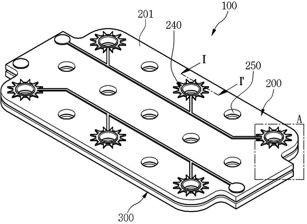
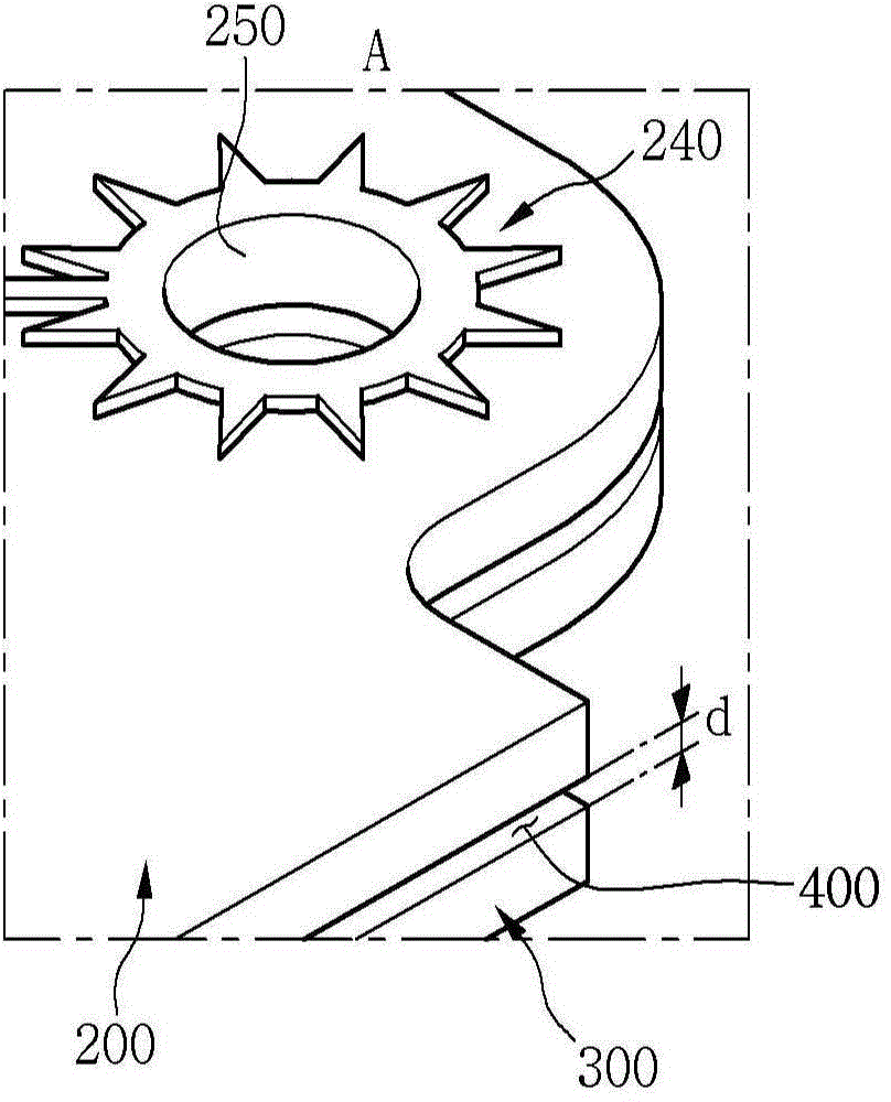
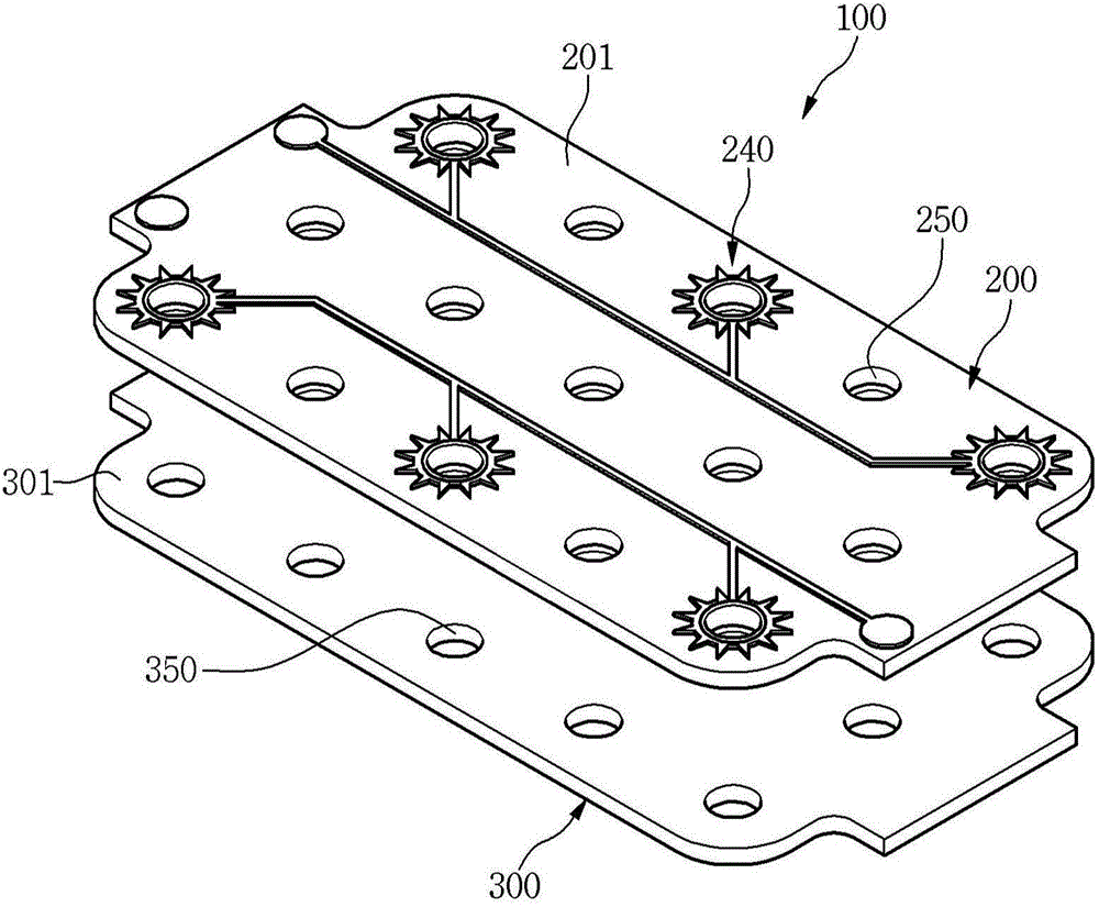
[0043] figure 1 is a perspective view showing the structure of a plasma electrode device according to an embodiment of the present invention, figure 2 to enlarge figure 1 Part "A" of the drawings, image 3 It is an exploded perspective view of the plasma electrode device of the embodiment of the present invention.

[0044] refer to Figure 1 to Figure 3 The plasma electrode device 100 according to the embodiment of the present invention includes a first substrate 200 and a second substrate 300 arranged to face each other. As an example, the second substrate 300 is disposed on the lower side o...


PUM


Abstract

Provided are a plasma electrode device and a manufacturing method thereof. The plasma electrode device includes a first substrate including a first substrate main body having a first flow hole through which air flows and a first discharge electrode disposed on one surface of the first substrate main body and a second substrate disposed on one side of the first substrate, the second substrate including a second flow hole through which air flows and a second discharge electrode acting with the first substrate. The first substrate main body includes a ground electrode acting with the first or second discharge electrode to perform plasma discharge and a first insulator coupled to the ground electrode.

Description

technical field [0001] The invention relates to plasma electrode arrangements. Background technique [0002] Recently, in order to save energy, buildings are made airtight by minimizing the introduction of outside air, resulting in increasing indoor air pollution. Therefore, various legal regulations on indoor pollutants are increasingly strengthened. [0003] On the other hand, during the operation of home appliances installed in homes, companies, etc., indoor pollutants may be generated and deposited inside the home appliances, or discharged from the home appliances. Such indoor pollutants cause unpleasant smells and have a bad effect on the hygiene of users. For example, in the case of home appliances using air or water containing moisture, such as air conditioners, dehumidifiers, air cleaners, refrigerators, and washing machines, contamination by dust or microorganisms occurs inside or outside the home appliances. [0004] In detail, the above-mentioned indoor polluta...

Claims


Application Information

Patent Timeline
Patent Type & Authority Applications(China)
IPC IPC(8): H05H1/24
CPCB01J2219/1203B01D53/32F24F3/166B01J2219/0894B03C3/38H01J37/32055H01J37/3244B03C3/41A61L2/088B01J19/127A61L9/22B01D53/323B01D53/8675B01D2257/504B01D2257/708B01D2257/91B01D2259/4508F24F8/192Y02A50/20H05H1/2418B03C3/32B03C3/40B01D2259/818
Inventor 张在洙成奉祚
Owner LG ELECTRONICS INC
Learn More