Novel electronic cigarette

An electronic cigarette, a new type of technology, applied in tobacco, smoker supplies, applications, etc., can solve the problems of insufficient length of resistance wire, high power of resistance wire, and short life of e-cigarettes, and overcome the complex structure of temperature control circuit and constant temperature. Fast heat generation and high heat conversion rate

Active Publication Date: 2015-10-07
CHINA TOBACCO YUNNAN IND
View PDF10 Cites 2 Cited by
  • Summary
  • Abstract
  • Description
  • Claims
  • Application Information

AI Technical Summary

Problems solved by technology

Although the method of heating the resistance wire is simple and easy, but limited by the volume capacity of the battery in the electronic cigarette and the volume of the electronic cigarette, the heating resistance wire cannot be made with a large power, and the length of the resistance wire is limited, which is prone to the problem of insufficient smoke in the electronic cigarette
On the other hand, there is a high difference between the vaporization temperature of the e-cigarette liquid and the conduction temperature of the heating resistance wire. Therefore, it is necessary to add temperature control and detection circuits and components to the e-cigarette, which also increases the cost of the e-cigarette. and complexity, otherwise when the smoke liquid in an electronic cigarette is critically exhausted, it is easy to cause the resistance wire to burn dry, and it is very easy to cause the resistance wire to burn out; in addition, after the circuit components are miniaturized, the reliability of the components is reduced, Even some well-designed and reusable rechargeable electronic cigarettes often have temperature control failures, which inevitably lead to a short lifespan

Method used


Image

  • Novel electronic cigarette
  • Novel electronic cigarette
  • Novel electronic cigarette

Examples


Embodiment Construction

[0021] The following will clearly and completely describe the technical solutions in the embodiments of the present invention with reference to the accompanying drawings in the embodiments of the present invention. Obviously, the described embodiments are only some, not all, embodiments of the present invention. Based on the embodiments of the present invention, all other embodiments obtained by persons of ordinary skill in the art without making creative efforts belong to the protection scope of the present invention.

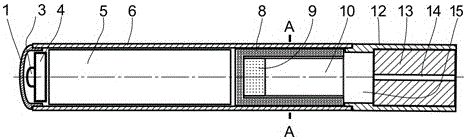
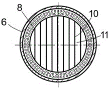
[0022] figure 1 and figure 2 The new electronic cigarette shown includes a tubular tobacco rod 6, a suction nozzle connected to one end of the tobacco rod 6, a smoking device and a battery arranged in sequence in the tobacco rod 6 from the end of the tobacco rod 6 close to the suction nozzle to the end far from the suction nozzle. 5. The air pressure switch 4, the LED light 3, and the transparent or translucent ventilation cover 1 with the air intake hole ar...


PUM


Abstract

The invention discloses a novel electronic cigarette, and aims to provide a novel electronic cigarette being long in service life. The novel electronic cigarette comprises a tube tobacco rod, a suction nozzle connected at one end of the tobacco rod, a smoke emitting device, a battery, a wind pressure switch and an LED lamp which are sequentially disposed in the tobacco rod from the end, close to the suction nozzle, of the tobacco rod, to the end, far away from the suction nozzle, of the tobacco rod, and a transparent or semitransparent ventilating cover which has vents and is disposed at the end of the tobacco rod. The joint of the tobacco rod and the suction nozzle is provided with a smoke mixing cavity. The suction nozzle comprises a tube body and a suction nozzle inner core fully filled in the tube. The smoke emitting device comprises a heat insulation sleeve sleeved in the tobacco rod, a PCT heater and a radiator, wherein the PCT heater and the radiator are disposed in the heat insulation sleeve and connected through thermal conduction. The PCT heater is arranged at one side, far away from the smoke mixing cavity, of the heat insulation sleeve, and the radiator is arranged one side, close to the smoke mixing cavity, of the heat insulation sleeve. The wind pressure switch, the LED lamp, the battery and the PCT heater are electrically connected. The novel electronic cigarette is quick in heating, high in heat transformation rate and long in service life without open fire.

Description

technical field [0001] The invention relates to the technical field of novel cigarette equipment, in particular to a novel electronic cigarette. Background technique [0002] Most of the existing e-cigarettes are heated by resistance wires, so that the accompanying e-cigarette liquid is vaporized to meet the needs of e-cigarette smoking. Although the resistance wire heating method is simple and easy to implement, due to the limitation of the volume capacity of the battery in the electronic cigarette and the volume of the electronic cigarette, the heating resistance wire cannot be made with high power, and the limited length of the resistance wire is prone to the problem of insufficient smoke in the electronic cigarette. On the other hand, there is a high difference between the vaporization temperature of the e-cigarette liquid and the conduction temperature of the heating resistance wire. Therefore, it is necessary to add temperature control and detection circuits and compon...

Claims


Application Information

Patent Timeline
Patent Type & Authority Applications(China)
IPC IPC(8): A24F47/00
CPCA24F47/008
Inventor 吴俊黄立斌
Owner CHINA TOBACCO YUNNAN IND
Why Eureka
Try Eureka