Nanojet device based on pyroelectric effect, micro-nano-composite-jet device based on pyroelectric effect and control method of micro-nano-composite-jet device

A spraying device and nano-spraying technology, which is applied in the direction of spraying devices, spraying electric energy devices, liquid spraying devices, etc., can solve problems such as difficult composite use, application restrictions, and difficult conversion to micron spraying equipment, and achieve the effect of improving production efficiency

Inactive Publication Date: 2015-10-07
XIAMEN UNIV OF TECH
View PDF4 Cites 7 Cited by
  • Summary
  • Abstract
  • Description
  • Claims
  • Application Information

AI Technical Summary

Problems solved by technology

Micron-scale injection is to eject the liquid in the injection chamber by driving the diaphragm, etc. Jetting can achieve nanoscale resolution, but its application is limited due to the need for high-voltage circuits and complex electrodes
[0003] Aiming at the deficiencies of the existing nanoscale jetting devices, it is necessary to design a jetting device that can avoid many problems caused by the high voltage and complicated circuits required to directly apply the electric field
[0004] On the other hand, due to the difference in principle, nozzle structure and other auxiliary equipment between micro-jet and nano-jet, it is generally difficult to realize the combined use of the two in jet printing technology. When using a nano-jet device, even if some structures can use micro-jet, it is difficult to convert to micro-jet equipment, which will greatly reduce the jet efficiency

Method used


Image

  • Nanojet device based on pyroelectric effect, micro-nano-composite-jet device based on pyroelectric effect and control method of micro-nano-composite-jet device
  • Nanojet device based on pyroelectric effect, micro-nano-composite-jet device based on pyroelectric effect and control method of micro-nano-composite-jet device
  • Nanojet device based on pyroelectric effect, micro-nano-composite-jet device based on pyroelectric effect and control method of micro-nano-composite-jet device

Examples


Embodiment Construction

[0032] The present invention will be further described in detail below in conjunction with the accompanying drawings and specific embodiments. It should be noted here that the technical features involved in the various embodiments of the present invention described below can be combined with each other as long as they do not constitute conflicts with each other.

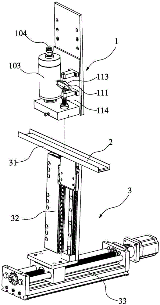
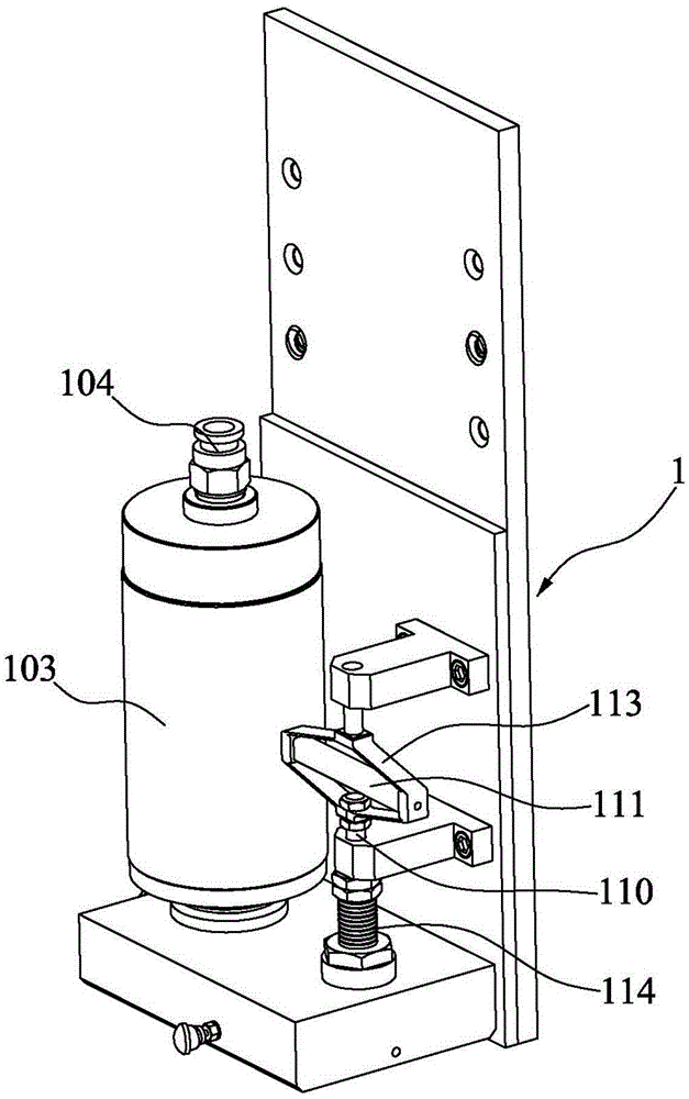
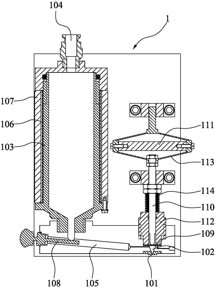
[0033] What the present invention discloses is a kind of nano jet device based on pyroelectric effect, such as Figure 1 to Figure 3 Shown is a preferred embodiment of the nanojet device of the present invention. The nano-injection device includes an injection mechanism 1, a pyroelectric crystal 2, a pressure source, a heat source and a control mechanism. in:

[0034] The injection mechanism 1 includes a nozzle 101, an injection chamber 102 and a storage tank 103, the nozzle 101 is arranged below the injection chamber 102, and the injection chamber 102 communicates with the material storage chamber in the storage t...


PUM


Abstract

The invention discloses a mechanism design of a nanojet device based on pyroelectric effect, a mechanism design of a micro-nano-composite-jet device based on pyroelectric effect and a control method of the micro-nano-composite-jet device. The nanojet device comprises a jet mechanism, a pyroelectric crystal, a pressure source, a heat source and a control mechanism. The nanojet device generates an electric field under the action of the heat source through the pyroelectric crystal, a solution is pulled out to form nano-scale liquid drops, and problems caused by high voltage and complicated circuit required when an electric field is directly applied to a traditional nanojet device can be avoided. A piezoelectric mechanism of a traditional jet device is further arranged on the micro-nano-composite-jet device. When micron-scale liquid drops need to be manufactured, the heat source is cut off so that micron-scale jet can be conducted, and then micro-nano-composite-transition is achieved.

Description

technical field [0001] The invention relates to the technical field of droplet spraying and free forming thereof, in particular to a mechanism design and control method of a pyroelectric effect-based nano-spray-micro-nano composite spraying device. Background technique [0002] Droplet ejection devices are widely used in printed circuit board manufacturing technology, display manufacturing technology, and inkjet printer technology. At present, droplet ejection devices are generally divided into micron-scale ejection and nano-scale ejection according to their ejection resolutions, and the ejection principles of the two are completely different. Micron-scale injection is to eject the liquid in the injection chamber by driving the diaphragm, etc. Jetting can achieve nanoscale resolution, but its application is limited due to the need for high-voltage circuits and complex electrodes. [0003] In view of the shortcomings of the existing nano-scale jetting devices, it is necessa...

Claims


Application Information

Patent Timeline
Patent Type & Authority Applications(China)
IPC IPC(8): B05B5/053B05B9/04B05B12/00
CPCB05B5/053B05B9/04B05B12/00
Inventor 谢丹常雪峰罗善明舒霞云王建郑康柯信福李挺勇
Owner XIAMEN UNIV OF TECH
Why Eureka
Try Eureka