
Automatic feeding and discharging device for bearing outer rings

A technology of automatic loading and unloading and bearing outer ring, which is applied in the direction of metal processing equipment, grinding workpiece support, manufacturing tools, etc., can solve the problems of affecting work efficiency, prone to failure, difficult to control, etc., to reduce labor force, prevent splashing, The effect of easy maintenance

Active Publication Date: 2015-10-07
GUANGZHOU UNIVERSITY
View PDF8 Cites 15 Cited by
  • Summary
  • Abstract
  • Description
  • Claims
  • Application Information

AI Technical Summary

Problems solved by technology

The whole device uses multiple cylinders to drive the mechanism to realize automatic loading and unloading, which improves the degree of automation to a certain extent, but there is a problem that failures are prone to occur under the cylinder load state. When loading materials, the bearings need to be pushed into the feeding guide rail one by one through the cylinder, and then through the lifting The cylinder pulls the feeding guide rail to rotate and sends the bearing into the processing area. The structure is complex, difficult to control, and prone to failure, which will affect work efficiency.

Method used


Image

  • Automatic feeding and discharging device for bearing outer rings
  • Automatic feeding and discharging device for bearing outer rings
  • Automatic feeding and discharging device for bearing outer rings

Examples


Embodiment Construction

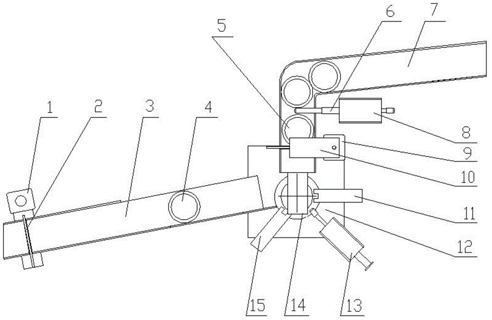
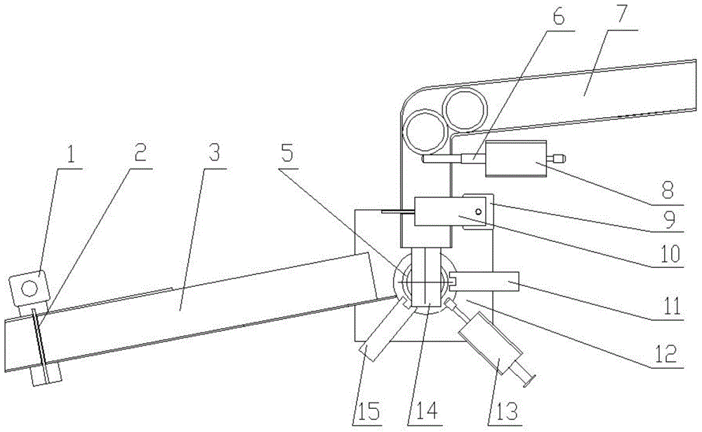
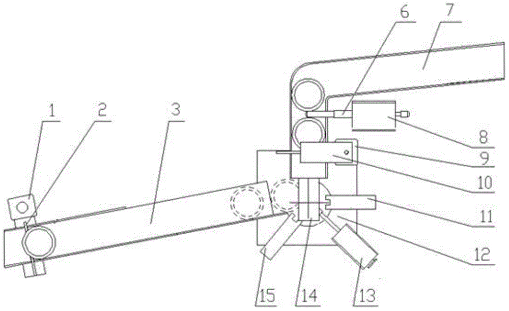
[0028] The present invention will be further described in conjunction with specific drawings and embodiments.

[0029] See figure 1 As shown, an automatic loading and unloading device for the outer ring of a bearing, including an upper material channel 7 and a lower material channel 3, the outlet end of the upper material channel (7) is docked with the processing area, and the entrance of the lower material channel (3) The end is docked with the processing area, and the middle end of the feeding channel 7 is provided with a feeding baffle rod 6 and a feeding baffle plate 10. The end is provided with a bearing baffle 14, and the feeding baffle 10 isolates the bearing to be processed from the processing area to prevent the grinding liquid from splashing during the processing. The bearing baffle 14 guides the bearing to be processed to slide down to the processing area, and prevents the bearing after processing. Roll out of the processing area, the end of the blanking channel 3 ...


PUM


Abstract

The invention relates to an automatic feeding and discharging device for bearing outer rings. The automatic feeding and discharging device for the bearing outer rings comprises a feeding track and a discharging track. The outlet end of the feeding track is in butt joint with a machining area. The inlet end of the discharging track is in butt joint with the machining area. A feeding stop lever and a feeding baffle are arranged at the middle end of the feeding track. The feeding stop lever is located above the feeding baffle. A bearing baffle is arranged at the tail end of the feeding track. The feeding baffle is used for isolating bearings to be machined from the machining area, so that grinding fluid is prevented from splashing during machining. The bearing baffle is used for guiding the bearings to be machined to slide downwards into the machining area and preventing the bearings from rolling out of the machining area after the bearings are machined. A discharging baffle is arranged at the tail end of the discharging track and is used for opening or closing an outlet of the discharging track, so that sealing is achieved in the machining process, and the grinding fluid is prevented from leaking outside. According to the automatic feeding and discharging device for the baring outer rings, automatic continuous feeding and discharging of the bearings can be achieved, rapidness and accuracy are guaranteed, the sealing performance is improved, and the grinding fluid is effectively prevented from splashing outwards or leaking outwards in the machining process; the structure is simple, operation is convenient, and labor intensity is greatly reduced.

Description

technical field [0001] The invention belongs to the technical field of mechanical automatic production, and relates to an automatic loading and unloading device for bearings, in particular to an automatic loading and unloading device for bearing outer rings. Background technique [0002] The degree of automation of modern bearing processing equipment is getting higher and higher, and the automatic loading and unloading mechanism of bearings is required to be more reasonable, simple and efficient. Usually, the bearing loading and unloading device uses multiple hydraulic cylinders to drive the manipulator or multiple combined mechanisms. The structure is complex, the energy consumption is large, the effect is small, and the failure rate is high, and maintenance is difficult, thus affecting the processing efficiency and production cost. [0003] The patent application number is 201310278502.6, which discloses an automatic loading and unloading device for a large-size bearing in...

Claims


Application Information

Patent Timeline
Patent Type & Authority Applications(China)
IPC IPC(8): B24B5/35B24B41/06
CPCB24B5/355B24B41/06
Inventor 刘晓初温溢恒姬武勋刘长红冯明松张建文
Owner GUANGZHOU UNIVERSITY
Learn More