
Superelastic decorative cable and its manufacturing and installation method

A production method and super-elastic technology, which is applied in the field of decorative cables, can solve the problems of affecting aesthetic requirements, uneven cables, and influence of tower beams, etc., and achieve the effect of convenient cable replacement, straight cables, and reasonable structure

Active Publication Date: 2017-01-04
LIUZHOU OVM MASCH CO LTD
View PDF5 Cites 0 Cited by
  • Summary
  • Abstract
  • Description
  • Claims
  • Application Information

AI Technical Summary

Problems solved by technology

[0002] In order to meet the needs of urban landscape, more and more decorative cables appear in the design of bridges; the main characteristics of the cables are that the appearance of the cable body should match the actual bridge, and the second is that the cable force of the cables during operation It is small and does not produce a large tensile force with the deformation of the structure; and the current conventional cables cannot meet the above conditions at the same time. , the cable is not straight and affects the aesthetic requirements; if a small-sized cable is selected, other conditions need to be added to meet the appearance matching. In addition, the risk of cable breakage will increase due to the increase in cable force , will cause additional impact on the tower beam

Method used


Image

  • Superelastic decorative cable and its manufacturing and installation method
  • Superelastic decorative cable and its manufacturing and installation method
  • Superelastic decorative cable and its manufacturing and installation method

Examples


Embodiment 1

[0088] A superelastic decorative cable with fork lug structure at both ends:

[0089] Such as figure 1 As shown, the basic structure of the superelastic decorative cable with the lug structure at both ends includes an anchor cable body 4, two anchor assemblies positioned at both ends of the anchor cable body 4 and a sleeve outside the anchor cable body 4, Support ring 3 and a superelastic adjustment device 6 in the casing;

[0090] The two anchor assemblies 1 positioned at the two ends of the anchor cable body 4 are fork ear assemblies 11, and the superelastic adjustment device 6 is located in the lower casing, and one end of the lower casing 5 extends into the upper casing 2, and the superelastic adjustment device 6 One end is connected to the lower sleeve through the connector 611, and the other end is connected to the fork assembly 11 at the other end of the anchor cable body 4 through the connector 612 of the superelastic adjustment device 6. For the structure of the conn...

Embodiment 2

[0092] A superelastic decorative cable with lug structure at both ends of the cable length adjustment device:

[0093] Such as figure 2 As shown, the two anchor assemblies 1 located at the two ends of the anchor cable body 4 of the superelastic decorative cable with the fork lug structure at both ends are the fork lug assemblies 11. The difference from Embodiment 1 is that the superelastic adjustment device 6 is located in the upper casing 2, and there is a cable length adjusting device 7 in the lower casing 5. The cable length adjusting device 7 includes an adjusting sleeve 73, an adjusting rod I71 and an adjusting rod II72 respectively located at both ends of the adjusting sleeve 73. The adjusting rod I 71 is connected to the anchor cable body 4 , and one end of the adjusting rod II 72 is connected to the other end of the anchor cable body 4 through the positioning column 8 .

[0094] In the superelastic decorative cable described in Embodiment 1 or Embodiment 2, the ancho...

Embodiment 3

[0098] A method for making a superelastic decorative cable, which is a method for making a superelastic decorative cable with two ends fork lug structure described in Embodiment 1, it comprises the following steps:

[0099] Step 1: Lay the anchor cable body 4 flat on the bridge deck, install the support ring 3 on the flat anchor cable body 4 (see Figure 6 );

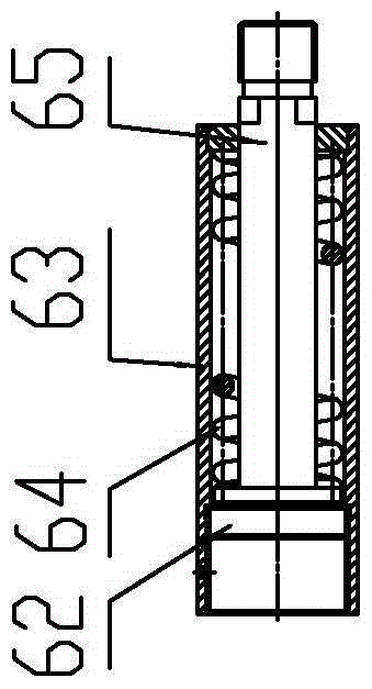
[0100] Step 2: Assemble the superelastic adjustment device 6; the superelastic adjustment device 6 is composed of a connector 61, a stopper 62, a casing 63, a superelastic body 64 and a pressing rod 65; place the stopper 62 and the pressing rod 65 in sequence into the casing 63, the superelastic body 64 is sleeved on the pressure rod 65 (see image 3 );

[0101] Step 3: Assemble the anchor cable body 4 and the super-elastic adjusting device 6; one end of the super-elastic adjusting device 6 is connected to one end of the anchor cable body 4 through the connector 611, and the anchor cable body 4 is connected to the sup...


PUM


Abstract

A hyper-elastic decorative stay cable comprises an anchor cable body, two anchoring modules, an upper casing, a lower casing and a supporting ring, wherein the two anchoring modules are positioned at the two ends of the anchor cable body; the upper casing is positioned outside the anchor cable body; the supporting ring is positioned in the upper casing or the lower casing; and one end of the upper casing is connected with a lug module at one end of the anchor cable body. The hyper-elastic decorative stay cable further comprises a hyper-elastic adjusting device positioned in the upper casing or the lower casing, wherein the hyper-elastic adjusting device comprises a connecting head stopping block, a casing, a hyper-elastic body and a pressing rod; a connecting head is a cylinder with unequal diameters; an external thread connected with the lower casing or the casing of the hyper-elastic adjusting device is arranged outside the connecting head; a through hole allowing the anchor cable to pass through is formed in the middle of the connecting head; a big boss used as a stressed surface of the hyper-elastic body is arranged at one end of the pressing rod; and the other end of the pressing rod is connected with the lug module through a thread connecting method. The hyper-elastic decorative stay cable provided by the invention is advantaged in that the structure is reasonable; the cable satisfies requirements on appearance and dimension of the cable body; no great additional tension is generated on the structure; the cable is convenient to replace; and the length and the force of the cable are convenient to adjust.

Description

technical field [0001] The invention relates to a decorative cable with little bearing capacity or no stress, in particular to a superelastic decorative cable for a landscape bridge and a manufacturing and installing method thereof. Background technique [0002] In order to meet the needs of urban landscape, more and more decorative cables appear in the design of bridges; the main characteristics of the cables are that the appearance of the cable body should match the actual bridge, and the second is that the cable force of the cables during operation It is small and does not produce a large tensile force with the deformation of the structure; and the current conventional cables cannot meet the above conditions at the same time. , the cable is not straight and affects the aesthetic requirements; if a small-sized cable is selected, other conditions need to be added to meet the appearance matching. In addition, the risk of cable breakage will increase due to the increase in ca...

Claims


Application Information

Patent Timeline
Patent Type & Authority Patents(China)
IPC IPC(8): E01D19/16E01D21/00
Inventor 石伟杨雄文华剑平王瀚德廖松山郑国坤覃磊梁黎霞
Owner LIUZHOU OVM MASCH CO LTD
Learn More