Novel supporting device for gas drilling sand draining pipe

A technology of gas drilling and supporting devices, which is applied in the direction of pipeline support, earthwork drilling, and flushing of boreholes, etc. It can solve the problems of difficult hoisting, large suspension span, and long distance from the combustion pit path, and achieves the goal of improving suspension stability. Effect

Inactive Publication Date: 2015-10-07
SOUTHWEST PETROLEUM UNIV
View PDF5 Cites 4 Cited by
  • Summary
  • Abstract
  • Description
  • Claims
  • Application Information

AI Technical Summary

Problems solved by technology

However, the bypass of the rotary control head is high from the ground and far away from the combustion pit path, and it needs to cross mud tanks and other equipment. Therefore, the sand discharge pipeline has the characteristics of large height drop and large suspended span. In addition, the sand discharge pipeline adopts a large size Steel pipes (large length, high rigidity, and heavy weight), use traditional triangular support frames to install sand discharge pipelines, such as figure 1 As shown in the figure, 1-wellhead device, 2-rotary control head, 3-triangular support frame, 4-mud tank, 5-burning and drainage tank, the triangular support frame is set under the sand discharge pipeline, the wellhead device and the burning and discharging tank There are multiple triangular support frames between the pools. Due to the difficulty in changing the support height of the triangular support frames and the inability to wrap the fixed and inclined sand discharge pipeline, there are engineering technical problems such as difficult hoisting, long labor hours, and poor suspension stability.

Method used


Image

  • Novel supporting device for gas drilling sand draining pipe
  • Novel supporting device for gas drilling sand draining pipe
  • Novel supporting device for gas drilling sand draining pipe

Examples


Embodiment Construction

[0024] The present invention will be further described below in conjunction with accompanying drawing, protection scope of the present invention is not limited to the following:

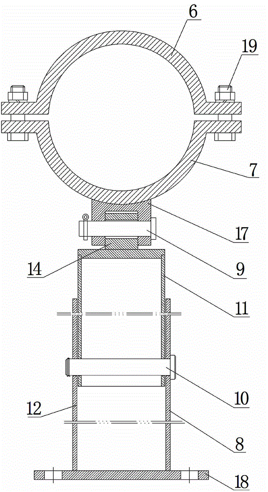
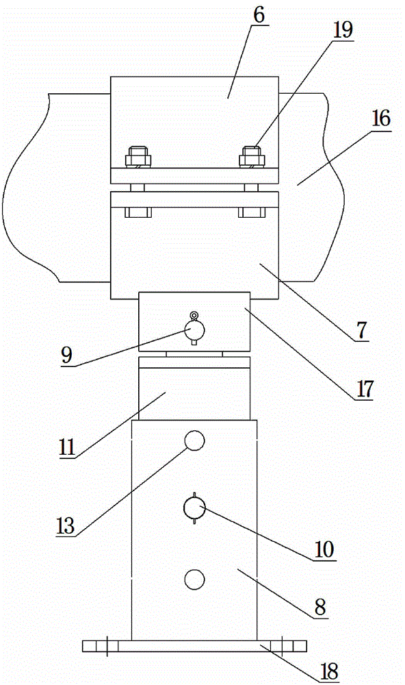
[0025] Such as figure 2 , 3 , 4, 9, 10, 11, 12, and 13, a new type of support device for gas drilling sand discharge pipeline, which includes an upper pressure sleeve 6, a lower support sleeve 7, a support base 8, an angle rotation pin 9, a fixed height The pin 10 and the height adjustment sleeve 11, the support base 8 is columnar, the top of the support base 8 is provided with a cavity 12, and a plurality of penetrating supports are provided on the cylindrical surface of the support base 8 and along the length direction of the support base 8 The through hole I13 of the base 8, the top of the height adjustment sleeve 11 is provided with a double-hole hinged seat 14, the cylindrical surface of the height adjustment sleeve 11 and along the length direction of the height adjustment sleeve 11 are provi...


PUM


Abstract

The invention discloses a novel supporting device for a gas drilling sand draining pipe. The novel supporting device comprises an upper pressing sleeve (6), a lower supporting sleeve (7), a supporting base (8) and a height adjusting sleeve (11). A plurality of through holes I (13) penetrating through the supporting base (8) are formed in the cylindrical surface of the supporting base (8) in the length direction of the supporting base (8). A plurality of through holes II (15) penetrating through the height adjusting sleeve (11) are formed in the cylindrical surface of the height adjusting sleeve (11) in the length direction of the height adjusting sleeve (11). The height adjusting sleeve (11) is fixed into a cavity (12) through a height fixing pin (10) which penetrates through any through hole I (13) and the corresponding through hole II (15). The upper pressing sleeve (6) is fixed to the lower supporting sleeve (7) through connecting bolts (19). The bottom of the lower supporting sleeve (7) is further provided with a single-hole hinge support (17). The novel supporting device has the advantages that the mounting difficulty is lowered, the construction time is shortened, the suspension stability is improved, and safety and reliability are achieved.

Description

technical field [0001] The invention relates to a wellhead device in the field of oil and gas well engineering, in particular to a novel support device for a gas drilling sand discharge pipeline. Background technique [0002] At present, gas drilling needs to install a rotary control head on the annular blowout preventer, and connect the sand discharge pipeline through the bypass of the rotary control head to provide an exhaust channel for the wellbore. However, the bypass of the rotary control head is high from the ground and far away from the combustion pit path, so it needs to cross mud tanks and other equipment. Therefore, the sand discharge pipeline has the characteristics of large height drop and large suspended span. In addition, the sand discharge pipeline adopts a large size Steel pipes (large length, high rigidity, and heavy weight), use traditional triangular support frames to install sand discharge pipelines, such as figure 1 As shown in the figure, 1-wellhead d...

Claims


Application Information

Patent Timeline
Patent Type & Authority Applications(China)
IPC IPC(8): E21B21/00F16L3/10F16L3/16
Inventor 刘绘新樊东昌刘璞赖汶龙邓韦克
Owner SOUTHWEST PETROLEUM UNIV
Why Eureka
Try Eureka