Automatic tracking solar heat collector pedestal

A solar heat collector and automatic tracking technology, which is applied in the direction of solar thermal power generation, solar thermal devices, heating devices, etc., can solve problems such as the reduction of heat collection efficiency of heat collectors, extend the time of receiving sunlight, and improve heat collection efficiency Effect

Active Publication Date: 2015-10-07
XI'AN UNIVERSITY OF ARCHITECTURE AND TECHNOLOGY
View PDF5 Cites 19 Cited by
  • Summary
  • Abstract
  • Description
  • Claims
  • Application Information

AI Technical Summary

Problems solved by technology

[0005] The heat collectors in the prior art often adopt a fixed structure, which can only ensure the collection of solar energy when the sun directly shines on the heat collector during the day. Once the sun cannot directly shine on the heat collector, the heat collector thermal efficiency will decrease

Method used


Image

  • Automatic tracking solar heat collector pedestal
  • Automatic tracking solar heat collector pedestal
  • Automatic tracking solar heat collector pedestal

Examples


Embodiment 1

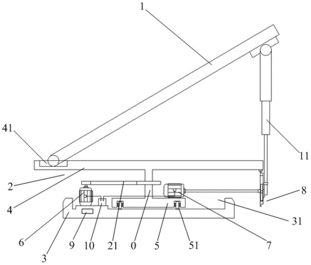
[0040] The present invention provides a self-tracking solar heat collector base, which is used to carry a solar heat collector 1, such as figure 1 As shown, the self-tracking solar collector base includes:

[0041] An I-shaped support 2 and a base 3, the I-shaped support 2 is located above the base 3;

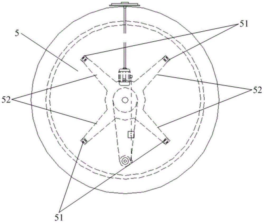
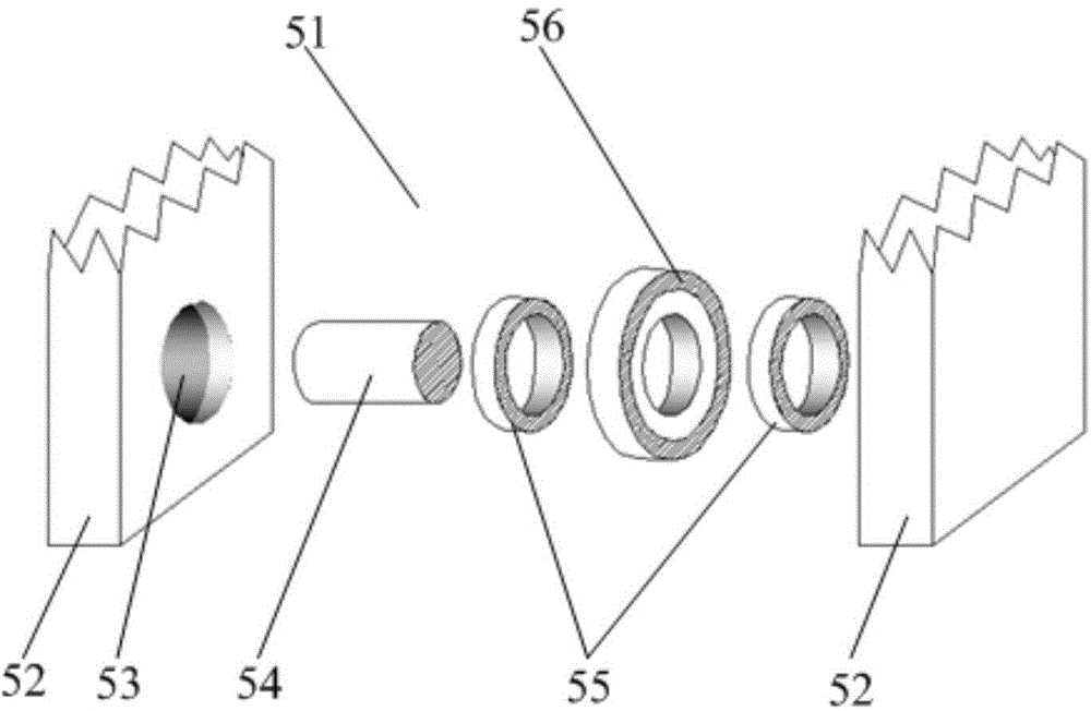
[0042] The I-shaped bracket 2 is divided into an upper layer 4, a lower layer 5, and a central axis body 0 connecting the upper layer 4 and the lower layer 5, and the surface edge of the upper layer 4 of the I-shaped bracket is provided with a 1 sliding chute 41 at the bottom, the lower layer 5 of the I-shaped support is provided with rollers 51, the lifting motor 7 arranged on the I-shaped support 2 passes through the planetary gear set 8 and the top of the solar collector 1 The support rod 11 is connected;

[0043] The middle part of the base 3 is provided with a rolling groove 31 for the movement of the roller 51, and the rotating motor 6 arranged on the edge of the base 3...

Embodiment 2

[0082] The present invention provides a detailed method for using the base of an automatic tracking solar collector, specifically as follows:

[0083] 1 servo motor speed

[0084] Figure 7a The angle relationship between the sun's incident direction and the collector is explained, and the known sun altitude angle h is:

[0085]

[0086] in, is the geographic latitude, δ is the solar declination angle, and ω is the solar hour angle.

[0087] Such as Figure 7b As shown, the sun azimuth r expression is:

[0088] sin r = cos δ sin ω cosh

[0089] (1) Day time (T1-T2 time, T1 and T2 are local sunrise and sunset respectively):

[0090] Speed ​​n of lifting motor 7 1 for:

[0091] n 1 = rθ 360 · RΔt ...


PUM


Abstract

The invention discloses an automatic tracking solar heat collector pedestal, and belongs to the energy collection field; the automatic tracking solar heat collector pedestal comprises a H-shape support and a pedestal; a sensitization assembly can monitor the sun mobile conditions, and sends the mobile conditions to a motor control module, thus respectively controlling a rotary motor and a lifting motor, arranged in the solar heat collector pedestal, to operate; therefore, the solar heat collector carried by the solar heat collector pedestal can be directly irradiated by the sun in a long time, thus prolonging sun light irradiation reception time, and improving heat collector thermal-arrest efficiency.

Description

technical field [0001] The invention relates to the field of energy collection, in particular to an automatic tracking solar heat collector base. Background technique [0002] Today, as fossil fuels are becoming increasingly depleted, solar energy, as a renewable energy source, has become an important part of human energy utilization. In recent years, solar thermal utilization has developed particularly rapidly. Heat collectors are the basic components of solar thermal utilization systems. It directly determines the collection of solar light and heat by the system, so it is of great significance to improve the heat collection efficiency of the heat collector. [0003] Flat-plate collectors and vacuum tube collectors are currently the most widely used forms of solar collectors. When the two types of collectors are placed, the deviation angle from the due south direction is required to be no more than 15°, and they are generally placed in a fixed position due to the south. Bo...

Claims


Application Information

Patent Timeline
Patent Type & Authority Applications(China)
IPC IPC(8): F24J2/52F24J2/54
CPCY02E10/47
Inventor 刘艳峰陈迎亚王登甲王敏
Owner XI'AN UNIVERSITY OF ARCHITECTURE AND TECHNOLOGY
Why Eureka
Try Eureka