AFM probe array integrated with ultrasonic energy transducers

A technology of ultrasonic transducer and probe array, which is applied in scanning probe technology, scanning probe microscopy, using sound wave/ultrasonic wave/infrasonic wave to analyze solids, etc. Internal imaging and other problems, to achieve the effect of speeding up scanning imaging speed, solving slow speed, and improving resolution

Active Publication Date: 2015-10-07
INST OF SEMICONDUCTORS - CHINESE ACAD OF SCI
View PDF18 Cites 7 Cited by
  • Summary
  • Abstract
  • Description
  • Claims
  • Application Information

AI Technical Summary

Problems solved by technology

[0004] Aiming at the problems that AFM cannot image the interior and the scanning speed of a single pr

Method used


Image

  • AFM probe array integrated with ultrasonic energy transducers
  • AFM probe array integrated with ultrasonic energy transducers
  • AFM probe array integrated with ultrasonic energy transducers

Examples


Example Embodiment

[0030] Embodiment one

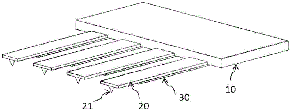
[0031] see again figure 1 , is a structural schematic diagram of Embodiment 1 of the present invention, wherein the ultrasonic transducer is a comb-shaped AFM probe array structure, including:

[0032] A base 10, the base 10 is rectangular;

[0033] A plurality of micro-cantilever beams 20, which are respectively connected to one side of the base 10, each micro-cantilever beam 20 is made with a needle tip 21 below the end;

[0034] A plurality of ultrasonic transducers 30, which are respectively fabricated on the back of a plurality of micro-cantilever beams 20 and or the back of the base 10;

[0035] Wherein a plurality of micro-cantilever beams 20 and a plurality of ultrasonic transducers 30 form a probe array.

Example Embodiment

[0036] Embodiment two

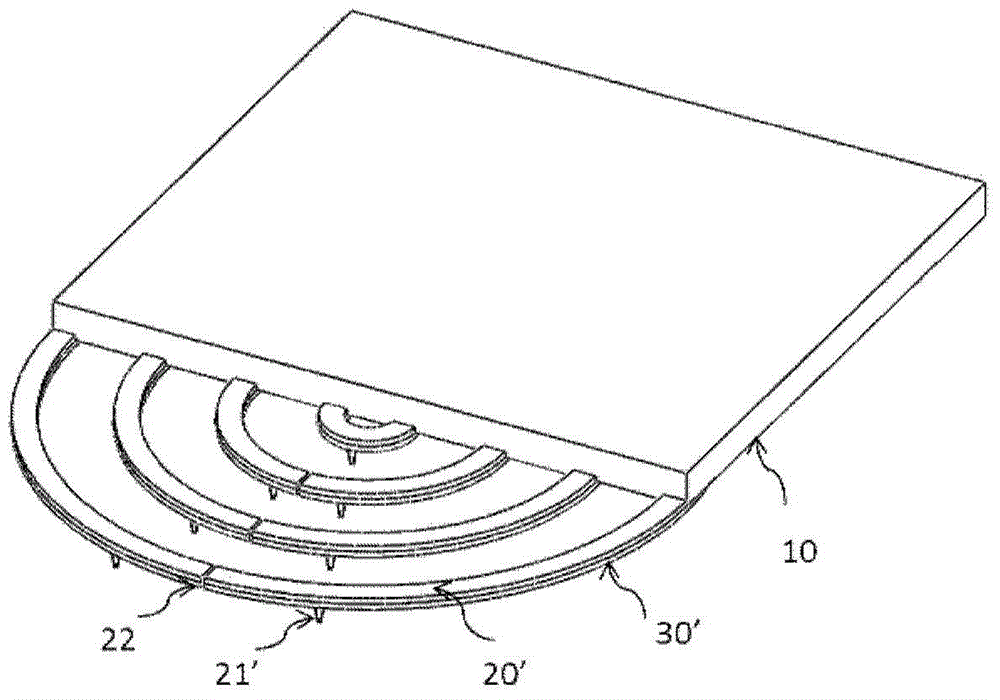
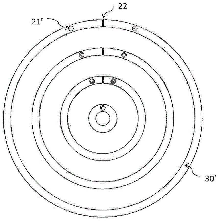
[0037] see again figure 2 and image 3 , is a structural schematic diagram of Embodiment 2 of the present invention, wherein the AFM probe array structure when the ultrasonic transducer is a ring type includes:

[0038] A base 10, the base 10 is rectangular;

[0039] A plurality of ring-shaped micro-cantilever beams 20' are respectively connected to one side of the base 10, and each ring-shaped micro-cantilever beam 20' is made with a needle point 21';

[0040] A plurality of ring-shaped ultrasonic transducers 30', which are respectively fabricated on the back of a plurality of ring-shaped micro-cantilever beams 20' and or the back of the base 10;

[0041] Wherein a plurality of annular micro-cantilever beams 20' and a plurality of annular ultrasonic transducers 30' form a probe array.


PUM

PropertyMeasurementUnit
Thicknessaaaaaaaaaa
Thicknessaaaaaaaaaa
Widthaaaaaaaaaa

Abstract

Provided is an AFM probe array integrated with ultrasonic energy transducer. The AFM probe array includes a base which is rectangular in shape; a plurality of micro-cantilevers which are connected with one side edge of the base, and a plurality of ultrasonic energy transducers, wherein each micro-cantilever is provided with a needle tip, the ultrasonic energy transducers are arranged on the back sides of the micro-cantilevers or the back side of the base, and the micro-cantilevers and the ultrasonic energy transducers form the probe array. The probe integrated with the ultrasonic energy transducers solves the problem of inside imaging of samples, and the array type probe structure improves the imaging speed.

Description

technical field [0001] The invention relates to the fields of atomic force microscope and ultrasonic detection, in particular to an AFM probe array integrating ultrasonic transducers. Background technique [0002] In 1986, G.Binnig and C.F.Quate successfully developed the atomic force microscope (Atom Force Microscope, AFM). AFM uses the interaction force between atoms to detect the surface morphology of samples, and can realize the atomic-level observation of the surface of conductors, semiconductors and insulator materials. However, the traditional AFM technology cannot detect the structural information inside the sample, and can only perform surface imaging analysis. Therefore, it is necessary to seek other means to detect the internal structural information of the sample. In addition, AFM imaging speed is also very important, and a single AFM probe scanning limits the imaging speed. [0003] Ultrasonic imaging technology uses ultrasonic signals to reflect when they prop...

Claims


Application Information

Patent Timeline
IPC IPC(8): G01Q60/38G01N29/06
Inventor 何欢张金英杨晋玲杨富华
Owner INST OF SEMICONDUCTORS - CHINESE ACAD OF SCI
Why Eureka
Try Eureka