Auxiliary measuring rod for converter valve conduction tests

A technology of conduction test and auxiliary measurement, which is applied in the direction of measuring electricity, measuring devices, and measuring electrical variables, etc. It can solve the problems of increased danger for test personnel, and achieve the effect of convenient and flexible testing, convenient testing, and increased convenience

Inactive Publication Date: 2015-10-07
SHANGHAI MUNICIPAL ELECTRIC POWER CO
View PDF3 Cites 7 Cited by
  • Summary
  • Abstract
  • Description
  • Claims
  • Application Information

AI Technical Summary

Problems solved by technology

However, the thyristor is in a relatively internal position in the valve tower. When testing a certain thyristor, the tester needs to spend a certain amount of time to clamp the test clip to both ends of the thyristor under test. The operation also increases certain dangers to the test personnel.

Method used


Image

  • Auxiliary measuring rod for converter valve conduction tests

Examples


Embodiment

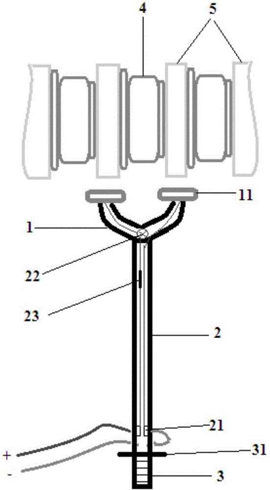
[0020] Such as figure 1 As shown, an auxiliary measuring rod for the conduction test of the converter valve is used for the test instrument to conduct the conduction test of a plurality of thyristors 4 in the converter valve. The auxiliary measuring rod includes a rod head 1, a rod body 2 and a The handle 3, the rod head 1 is a hollow U-shaped structure, the rod body 2 is a hollow telescopic rod, and the inside of the telescopic rod communicates with the inside of the rod head 1, and the two top ends of the rod head 1 are respectively provided with contact ends 11, and the contact ends 11 are respectively The wires pass through the rod head 1 and the inside of the telescopic rod in turn to connect with the testing instrument.

[0021] The contact end 11 is a metal end, the metal end is hinged with the top of the rod head 1, and its range of motion is 0-120 degrees. The spacing of the end aluminum blocks 5 is equal.

[0022] The contact end 11 on one top of the rod head 1 is ...


PUM


Abstract

The invention relates to an auxiliary measuring rod for converter valve conduction tests. The auxiliary measuring rod is applied to a situation in which a test instrument performs conduction tests on a plurality of thyristors in a converter valve. The auxiliary measuring rod comprises a rod head, a rod body and a handle which are successively connected with one another; the rod head is of a hollow U-shaped structure; the rod body is a hollow telescopic rod; the interior of the telescopic rod is communicated with the interior of the rod head; two top ends of the rod head are respectively provided with a contact end; and the contact ends respectively pass through the interiors of the rod head and the telescopic rod sequentially through wires so as to be connected with the test instrument. Compared with the prior art, the auxiliary measuring rod of the invention has the advantages of convenient and flexible testing, simple structure, convenient operation as well as being safe and reliable.

Description

technical field [0001] The invention relates to the field of electric equipment, in particular to an auxiliary measuring rod for the conduction test of a converter valve. Background technique [0002] Converter stations play a very important role in the power grid. As the core converter component of the converter station, the converter valve conducts a conduction test every year to test its conduction performance, so as to ensure that the converter station can deliver reliable energy to the grid. Due to the large volume of the converter valve and the large number of thyristors inside, a complete test usually requires thousands of conduction tests, and these tested devices are all placed in the air. Therefore, it is impossible to test each thyristor. Conduct the conduction test after disassembling separately. Usually, the tester takes the test equipment, takes the lift car to the position to be tested, and then clamps the test clips on both ends of the thyristor to be tested...

Claims


Application Information

Patent Timeline
Patent Type & Authority Applications(China)
IPC IPC(8): G01R1/02
Inventor 钱程晨倪汝冰时伟丽罗进蔡亦竹马千里龚震东
Owner SHANGHAI MUNICIPAL ELECTRIC POWER CO
Why Eureka
Try Eureka