
Assembly machine for commutator, meson and rotor assembly

A commutator and assembly machine technology, applied in the direction of electromechanical devices, electric components, manufacturing motor generators, etc., can solve the problems of unguaranteed product quality, inaccurate rotor positioning, low production capacity, etc., and achieve product yield rate The effect of upgrading, liberating labor force and improving production efficiency

Inactive Publication Date: 2017-07-18
深圳市鸿锦成自动化科技有限公司
View PDF4 Cites 0 Cited by
  • Summary
  • Abstract
  • Description
  • Claims
  • Application Information

AI Technical Summary

Problems solved by technology

Both methods have the following disadvantages: first, the production capacity is low; second, the rotor positioning is inaccurate and the product quality cannot be guaranteed

Method used


Image

  • Assembly machine for commutator, meson and rotor assembly
  • Assembly machine for commutator, meson and rotor assembly
  • Assembly machine for commutator, meson and rotor assembly

Examples


Embodiment 1

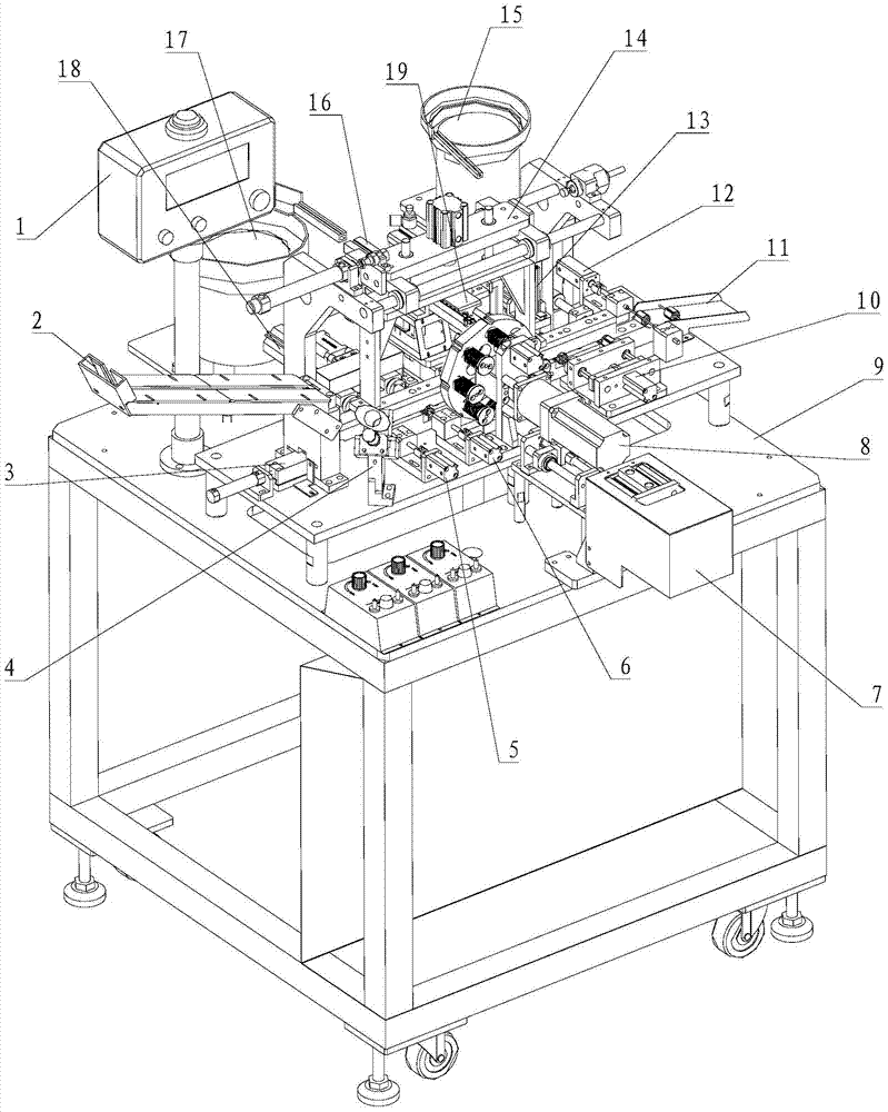
[0082] see Figure 1 to Figure 17 , Embodiment 1 of the present invention is:

[0083] A commutator, meson and rotor assembly machine, including a frame and a large working plate 9 arranged above the frame, and also includes a plurality of fixed rotors arranged in a line arranged on the large working plate 9 Seat 1406, the rotor feeding device arranged at one end of the rotor-sending fixed seat 1406, the rotor delivery mechanism 14 arranged above the rotor-sending fixed seat 1406, the rotor positioning device arranged at one side of the rotor-sending fixed seat 1406, and the The commutator press-in device, the meson press-in device, the glue dispensing mechanism 4, the meson vibrating plate 15, the commutator vibrating plate 17 and the finished product discharge channel 11 provided on the fixed seat 1406.

[0084] The displacement path of the rotor conveying mechanism 14 passes at least through the rotor positioning device, the commutator pressing device and the meson pressin...


PUM


Abstract

The invention discloses a commutator, meson and rotor assembling machine, which includes a frame and a large working plate arranged above the frame, and also includes a plurality of feeders arranged in a line arranged on the large working plate. The rotor fixing seat, the rotor feeding device arranged at one end of the sending rotor fixing seat, the rotor conveying mechanism arranged above the sending rotor fixing seat, the rotor positioning device arranged on the side of the sending rotor fixing seat, and the rotor sending device arranged along the sending rotor fixing seat The commutator press-in device and the meson press-in device; the displacement path of the rotor transport mechanism at least passes through the rotor positioning device, the commutator press-in device and the meson press-in device, and the rotor positioning device completes the positioning After positioning, the commutator is pressed onto the shaft branch at one end of the rotor through the commutator pressing device, and the meson is pressed onto the other shaft branch of the rotor through the meson pressing device. The invention liberates the labor force and greatly improves the production efficiency, and the yield rate of the manufactured products is greatly improved.

Description

technical field [0001] The invention relates to the technical field of micro-special motor manufacturing, in particular to an assembly machine for commutator, meson and rotor assembly. Background technique [0002] Assembly is the process of using equipment to make one material and another material form an assembly relationship through external force. At present, in the micro motor industry, there are two ways to assemble assembled rotors, commutators, and copper mesons: One is purely manual operation. First use tweezers to clamp a commutator into the fixed tooling, then use the other hand to put the rotor on the fixed tooling in a certain direction, press the switch, and the pneumatic punch will Next, press the commutator into the rotor, and then repeat the above action to press in the copper meson; the other is semi-automatic operation, first use the vibrating plate to send the commutator to the top of a movable push commutator rod, Then manually put the rotor in a fixed ...

Claims


Application Information

Patent Timeline
Patent Type & Authority Patents(China)
IPC IPC(8): H02K15/00
Inventor 姚国良
Owner 深圳市鸿锦成自动化科技有限公司
Learn More