Refrigerator
A technology of refrigerators and storage containers, applied in the field of refrigerators
- Summary
- Abstract
- Description
- Claims
- Application Information
AI Technical Summary
Problems solved by technology
Method used
Image
Examples
Embodiment approach 1
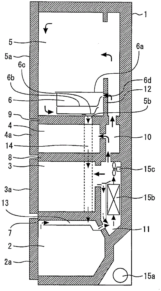
[0033] figure 1 It is a longitudinal cross-sectional view of the refrigerator according to Embodiment 1 of the present invention seen from the side direction.
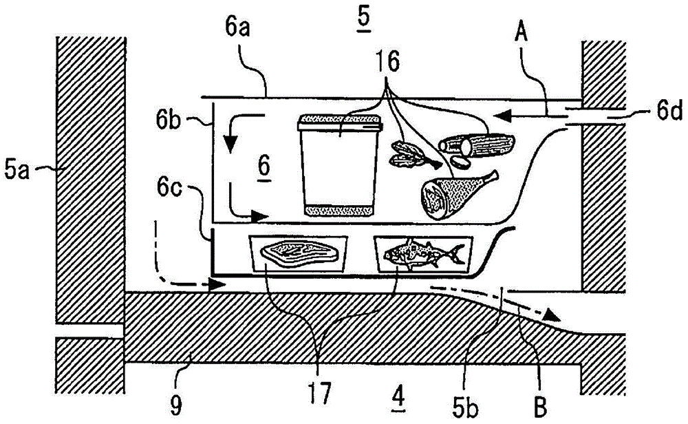
[0034] exist figure 1 Among them, the refrigerator 1 is provided with a plurality of storage compartments. For example, the storage room is composed of a vegetable room 2 , a freezer room 3 , a switching room 4 (freezing storage room), an ice room (not shown), a refrigerator room 5 , and a zero temperature room 6 .
[0035] The vegetable compartment 2 is located at the lower part of the refrigerator 1 . A door 2a is provided on the front side of the vegetable compartment 2 . Vegetable compartment 2 is formed to be able to be drawn toward the front side of refrigerator 1 together with door 2a. The freezer compartment 3 is located directly above the vegetable compartment 2 . The freezer compartment 3 is separated from the vegetable compartment 2 by a boundary wall 7 . A door 3a is provided on the front side of the ...
Embodiment approach 2
[0085] Figure 5 It is sectional drawing which looked at the zero temperature chamber of the refrigerator concerning Embodiment 2 of this invention from the side direction. In addition, the same code|symbol is attached|subjected to the same or equivalent part as Embodiment 1, and description is abbreviate|omitted.
[0086] The front surface of the first storage container 6b of Embodiment 2 is different from the front surface of the first storage container 6b of Embodiment 1. Specifically, the front surface of the first storage container 6b is formed of two plates 23 that are visually transparent. As a result, the front surface of the first storage container 6b is sealed. That is, a void is formed in the front surface of the first storage container 6b. This void functions as an insulating air layer.
[0087] The front surface of the second storage container 6c of Embodiment 2 is different from the front surface of the second storage container 6c of Embodiment 1. Specifical...
Embodiment approach 3
[0100] Figure 7 It is sectional drawing which looked at the zero degree chamber of the refrigerator concerning Embodiment 3 of this invention from the side direction. In addition, the same code|symbol is attached|subjected to the same or equivalent part as Embodiment 1, and description is abbreviate|omitted.
[0101] The second storage container 6c of Embodiment 3 is a storage container in which a plurality of plate-shaped fins 28 are added to the bottom surface of the second storage container 6c of Embodiment 1. As shown in FIG. A plurality of plate fins 28 are arranged on the upstream side of the suction port 5b.
[0102] Next, use Figure 8 A plurality of plate fins 28 will be described.
[0103] Figure 8 It is a perspective view of a main part of a refrigerator according to Embodiment 3 of the present invention.
[0104] Such as Figure 8 As shown, a plurality of plate fins 28 are formed in a plate shape. The plurality of plate fins 28 are formed of a material hav...
PUM
| Property | Measurement | Unit |
|---|---|---|
| Thermal conductivity | aaaaa | aaaaa |
Abstract
Description
Claims
Application Information
 - R&D
- Intellectual Property
- Life Sciences
- Materials
- Tech Scout
- Unparalleled Data Quality
- Higher Quality Content
- 60% Fewer Hallucinations
Browse by: Latest US Patents, China's latest patents, Technical Efficacy Thesaurus, Application Domain, Technology Topic, Popular Technical Reports.
© 2025 PatSnap. All rights reserved.Legal|Privacy policy|Modern Slavery Act Transparency Statement|Sitemap|About US| Contact US: help@patsnap.com


