Fixture for machining annular parts and method for machining parts through fixture

A ring-shaped part and fixture technology, used in metal processing machinery parts, manufacturing tools, metal processing equipment, etc., can solve the problems of inconvenient clamping and elastic deformation due to poor radial rigidity, and achieve the effect of avoiding processing errors and improving processing accuracy.

Inactive Publication Date: 2015-10-14
LUOYANG BEARING SCI & TECH CO LTD
View PDF6 Cites 8 Cited by
  • Summary
  • Abstract
  • Description
  • Claims
  • Application Information

AI Technical Summary

Problems solved by technology

[0003] The purpose of the present invention is to solve the problem that the radial rigidity of the bearing workpiece is poor, it is not easy to clamp, and the existing clamping is easy to cause elastic deformation, and to provide a fixture for processing ring parts and a method for processing parts using the fixture

Method used


Image

  • Fixture for machining annular parts and method for machining parts through fixture
  • Fixture for machining annular parts and method for machining parts through fixture
  • Fixture for machining annular parts and method for machining parts through fixture

Examples


Embodiment Construction

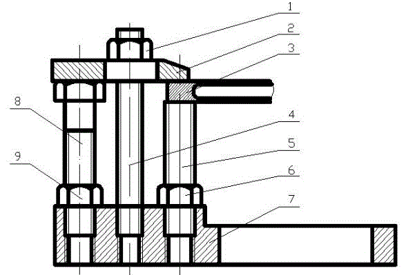
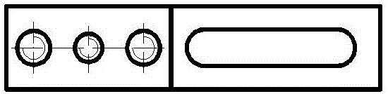
[0025] figure 1 , 2 Shown in and 3, the specific implementation is as follows:

[0026] A fixture for processing ring parts, including a support base 7 with a boss on the top, three support columns are installed on the boss, the three support columns are respectively support column I4, support column II8 and support column III5, support column I4, The length of the supporting column II8 and the supporting column III5 protruding from the boss decreases successively. A pressing plate 2 is installed on the top of the supporting column II8, and the pressing plate 2 is pressed on the top of the supporting column II8 through the pressing block 1 installed on the supporting column I4. And the bottom of one end of the pressing plate 2 cooperates with the top of the support column III5 to clamp the workpiece 3 to be processed.

[0027] The boss is provided with three installation holes I that run through the support base 7, the support column I4, the support column II8 and the suppor...


PUM


Abstract

The invention provides a fixture for machining annular parts and a method for machining the parts through the fixture. The fixture comprises a supporting base provided with a boss on the top. The boss is provided with three supporting columns, and the lengths of the three supporting columns are sequentially reduced. A pressing plate is installed on the top of the supporting column II. The pressing plate is pressed on the top of the supporting column II through a pressing block installed on the supporting column I. The bottom of one end of the pressing plate and the top of the supporting column III are matched to clamp the parts to be machined. The position of the pressing plate is adjusted through cooperation of the three supporting columns, and the pressing plate and the supporting column III are matched to press the parts to be machined, so multiple fixtures can be matched to clamp some annular parts inconvenient to fix, the fixture can be adjusted to adapt to parts in different sizes, machining errors caused by elastic deformation generated due to clamping and radial fixing when the annular parts are fixed are avoided, and machining precision of the annular parts is improved.

Description

technical field [0001] The invention relates to a fixture device for clamping workpieces on a lathe, in particular to a fixture for processing ring parts and a method for processing parts using the fixture. Background technique [0002] Vertical lathes generally use a four-jaw chuck to clamp and position the workpiece. The positioning uses four jaws to make radial contact with four points on the circumference of the workpiece, and the workpiece is clamped and positioned by applying a certain radial force at the contact point. Since the bearing parts are generally ring-shaped workpieces with poor radial rigidity, after being subjected to radial forces at four points, large elastic deformations will inevitably occur in the radial direction. When the workpiece is processed and the jaws are released, the radial elastic deformation of the workpiece will recover, which will affect the turning accuracy. This clamping method is difficult to meet the accuracy requirements of precisi...

Claims


Application Information

Patent Timeline
Patent Type & Authority Applications(China)
IPC IPC(8): B23Q3/06
CPCB23Q3/06B23Q2703/10
Inventor 张亚辉王淼王亚龙马元
Owner LUOYANG BEARING SCI & TECH CO LTD
Why Eureka
Try Eureka