Device for forming optical film layer integrated bands, and method thereof

A technology of optical film layers and laminates, applied in metal processing and other directions, can solve problems such as difficulty in suppressing local peeling of adhesive layers and release films

Active Publication Date: 2015-10-14
NITTO DENKO CORP
View PDF11 Cites 6 Cited by
  • Summary
  • Abstract
  • Description
  • Claims
  • Application Information

AI Technical Summary

Problems solved by technology

Therefore, this technology is not suitable for the optical film laminate that is the object of slitting in this application, that is, the optical film laminate that has an adhesive layer and a release film laminated on at least one side of the optical functional film, or at least one side of the optical functional film. An asymmetric o

Method used


Image

  • Device for forming optical film layer integrated bands, and method thereof
  • Device for forming optical film layer integrated bands, and method thereof
  • Device for forming optical film layer integrated bands, and method thereof

Examples


Embodiment 1

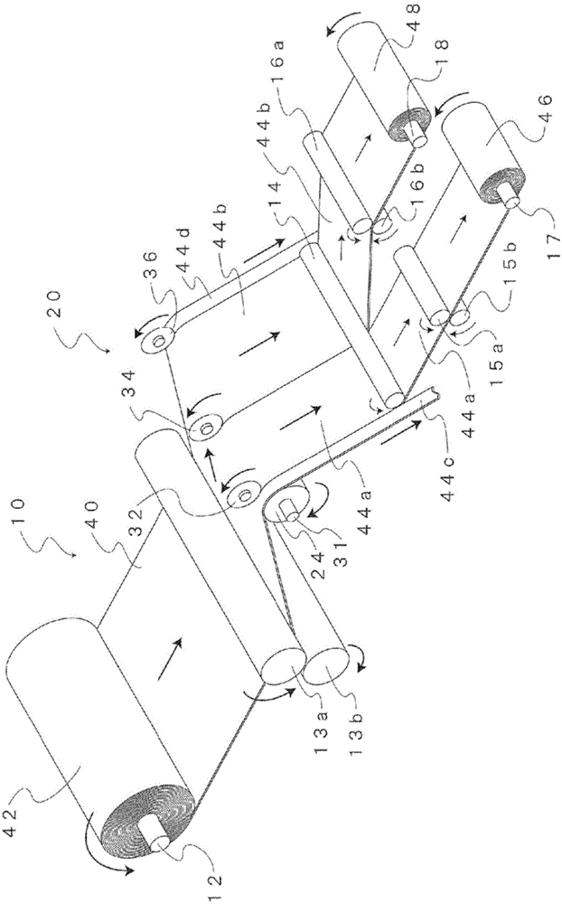
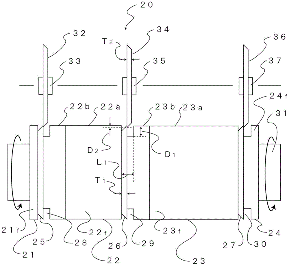
[0124] In the slitting machine of Example 1, a laminate support roll having a diameter of 98 mm on the outer peripheral surface against which the optical film laminate abuts and four grooves each having a diameter A first circular cutting knife having the same diameter as the outer peripheral surface. Second circular cutters having the same diameter as the first circular cutters are provided at positions corresponding to the respective first circular cutters. Therefore, the slitting machine in Embodiment 1 is equipped with four sets of first and second circular cutting knives. The knife tips of the first and second circular cutting knives are all acute-angled knife tips, and the angles of the knife tips are all made into 40 degrees. The distance between adjacent first circular cutters is 400 mm. The material of the first and second circular cutters is superhard material.

[0125] A strip-shaped optical film laminate with a width of 1330 mm is brought into contact with the o...

Embodiment 2

[0127] In the slitting machine of Example 2, the distance in the longitudinal direction at which the optical film laminate abuts against the outer peripheral surface of the laminate support roll was 12.8 mm (the angle of embrace was 15 degrees). Other conditions were the same as in Example 1.

Embodiment 3

[0129] In the slitting machine of Example 3, the diameter of the first circular cutter was made smaller than the diameter of the laminate support roll. The diameter of the first circular cutter is 96mm. Other conditions were the same as in Example 1.


PUM

PropertyMeasurementUnit
Diameteraaaaaaaaaa

Abstract

The invention provides a device for forming optical film layer integrated bands, and a method thereof, being able to improve the slitting precision of band-shaped optical film layer integrated body with high width and the uniformity of the facet shape at the end part of the highly slit band-shaped optical film layer integrated body. The device comprises a layer integrated body supporting roll, a plurality of first circular cutter knives and a plurality of second circular cutter knives. The layer integrated body supporting roll is provided with a peripheral surface connected with the optical film layer integrated body, and a plurality of grooves at the peripheral surface; each first circular cutter knife is provided with a closed angle point of a knife, and is arranged at the layer integrated body supporting roll and is arranged in each groove; and each second circular cutter knife is provided with a closed angle point of a knife, and is arranged at the position corresponding to the opposite side of the layer integrated body and the first circular cutter knife.

Description

technical field [0001] The present invention relates to an apparatus and method for forming optical film strips by cutting a strip-shaped optical film laminate into appropriate sizes. Background technique [0002] Optical functional films such as a polarizing film and a retardation film are used as optical components of an optical display device by being bonded to an optical display panel via an adhesive layer. Usually, a strip-shaped optical film laminate of a predetermined width including a release film, an adhesive layer, and an optical functional film is cut into a rectangular shape to form a sheet-shaped optical film laminate, and the release film is peeled off from the laminate, These optical functional films were thus obtained in a state with an adhesive layer. The strip-shaped optical film laminate having a predetermined width is formed by slitting a strip-shaped optical film laminate having a wider width than the predetermined width parallel to the longitudinal dir...

Claims


Application Information

Patent Timeline
IPC IPC(8): B26D1/22
Inventor 仲井宏太金起台崔忠烨朴孝浚金世渶
Owner NITTO DENKO CORP
Why Eureka
Try Eureka