Eureka AIR delivers breakthrough ideas for toughest innovation challenges, trusted by R&D personnel around the world.

Engine oil water-cooled housing type radiator of automobile transmission

A technology of automobile transmission and water-cooling cover, which is applied to mechanical equipment, gear lubrication/cooling, transmission parts, etc., can solve the problems of inconvenient maintenance and replacement, inability to meet the needs of oil heat dissipation, etc., to achieve convenient maintenance and replacement, and strengthen structural strength. , the effect of simple and compact structure

Inactive Publication Date: 2015-10-14
ANHUI TIANXIANG AIR CONDITIONING SCI & TECH CO LTD
View PDF7 Cites 0 Cited by
  • Summary
  • Abstract
  • Description
  • Claims
  • Application Information

AI Technical Summary

Problems solved by technology

[0004] With the development of automatic transmissions, the emergence of new types of transmissions with seven or more front speeds, and the advancement of continuously variable transmission technology, the above-mentioned water cooling method cannot meet the needs of engine oil heat dissipation due to the limitation of the size of the water tank of the car and the inconvenience of maintenance and replacement.

Method used


Image

  • Engine oil water-cooled housing type radiator of automobile transmission
  • Engine oil water-cooled housing type radiator of automobile transmission
  • Engine oil water-cooled housing type radiator of automobile transmission

Examples


Embodiment Construction

[0018] In order to easily understand the technical means, creative features, goals and effects of the present invention, the present invention will be further described below in conjunction with specific illustrations.

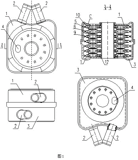
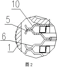
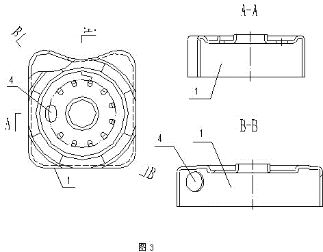
[0019] Such as Figure 1-6 As shown, the automobile transmission engine oil water-cooled shell radiator, which includes an upper cover 1 and a lower cover 3 with cooling water inlet and outlet 2 on the side, and an engine oil on the bottom plane of the upper cover 1 and the lower cover 3. The inlet and outlet 4, the upper cover 1 and the lower cover 3 are closed to form a water cavity, the water cavity is provided with a box piece 5 and a box piece 2 6, and the bottom left side of the box piece 5 has an outward protrusion and turns over Side hole 71, box piece one 5 bottom right side have outwardly protruding through hole 81, box piece two 6 bottom right sides have outwardly raised and flanging holes 72, box piece two 6 bottom left sides have Outwardly protru...


PUM


Abstract

The invention discloses an engine oil water-cooled housing type radiator of an automobile transmission. The engine oil water-cooled housing type radiator comprises an upper housing cover and a lower housing cover, wherein cooling water passing openings are formed in the side faces of the upper housing cover and the lower housing cover, engine oil passing openings are formed in the bottom planes of the upper housing cover and the lower housing cover, a water cavity is formed after the upper housing cover and the lower housing cover are combined and internally provided with first box pieces and second box pieces, an outward protruding flanging hole is formed in the left side of the bottom of each first box piece, an outward protruding through hole is formed in the right side of the bottom of each first box piece, an outward protruding flanging hole is formed in the left side of the bottom of each second box piece, and an outward protruding through hole is formed in the right side of the bottom of each second box piece. Each first box piece and the corresponding second box piece are oppositely overlapped, a space is formed in the middle of the first box piece and the second box piece, flow disturbing pieces are arranged in the space, and thus an engine oil chamber is formed. The flanging hole of one engine oil chamber is buckled with the through hole of another engine oil chamber, and the engine oil chambers are stacked in the way to form an engine oil chamber combination. An upper ejecting plate and a lower ejecting plate are installed on the upper portion and the lower portion of the engine oil chamber combination respectively. The engine oil water-cooled housing type radiator has the advantages of being simple in structure, good in radiating effect and convenient to maintain.

Description

technical field [0001] The invention relates to an automobile cooling device, in particular to an oil water-cooled casing radiator for an automobile transmission. Background technique [0002] Cars with an automatic transmission must be equipped with a transmission oil cooler, as the oil in an automatic transmission can overheat. Oil overheating can reduce transmission performance and even cause transmission damage. [0003] The oil radiator is a device that accelerates the heat dissipation of the lubricating oil to keep the temperature low. The purpose of installing this device is to avoid the weakening of lubricating effect caused by the increase of engine oil temperature. According to the different cooling media, the oil radiator can be divided into two types: air-cooled and water-cooled. Among them, the water-cooled type is usually an engine oil pipe, which is installed in the water chamber of the automobile water tank, and cools the high-temperature engine oil throug...

Claims


Application Information

Patent Timeline
Patent Type & Authority Applications(China)
IPC IPC(8): F16H57/04
CPCF16H57/0413F16H57/045
Inventor 骆宣佐陈添
Owner ANHUI TIANXIANG AIR CONDITIONING SCI & TECH CO LTD
Why Eureka
Eureka Blog
Learn More