Universal steel-plastic composite pipe piston pressure test device

A steel-plastic composite pipe and piston-type technology, which is applied in the direction of applying stable tension/pressure to test the strength of materials, can solve the problems of time-consuming, cumbersome, loose pressing blocks, etc., to avoid single repeated installation, avoid leakage, and seal good effect

Active Publication Date: 2017-11-17
安源管道实业股份有限公司
View PDF8 Cites 0 Cited by
  • Summary
  • Abstract
  • Description
  • Claims
  • Application Information

AI Technical Summary

Problems solved by technology

[0003] CN2565012Y shows a special pressure test tool for steel-plastic composite pipes. During the pressure test, as the test hydraulic pressure gradually increases, when the axial force borne by the lining core exceeds the pressure block and the pipe outer When the bite force between the plastic layers, the pressure block will loosen, which will cause leakage and fail the test
In addition, before each use of the special pressure test tool, it is necessary to assemble the inner lining core, pressing block, sleeve, sealing ring and other components one by one, which is very cumbersome and time-consuming
[0004] In addition, for different types of steel-plastic composite pipes, such as elbow steel-plastic composite pipes, straight steel-plastic composite pipes, multi-pass steel-plastic composite pipes, etc., it is necessary to design special pressure test equipment for pressure testing, which cannot Realize the pressure test of the above-mentioned various types of steel-plastic composite pipes with the same pressure test tool

Method used


Image

  • Universal steel-plastic composite pipe piston pressure test device
  • Universal steel-plastic composite pipe piston pressure test device
  • Universal steel-plastic composite pipe piston pressure test device

Examples


Embodiment Construction

[0025] The present invention will be described in further detail below in conjunction with the accompanying drawings.

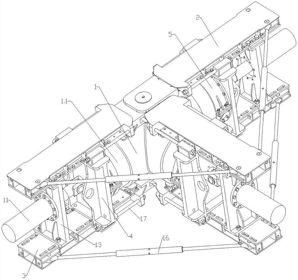
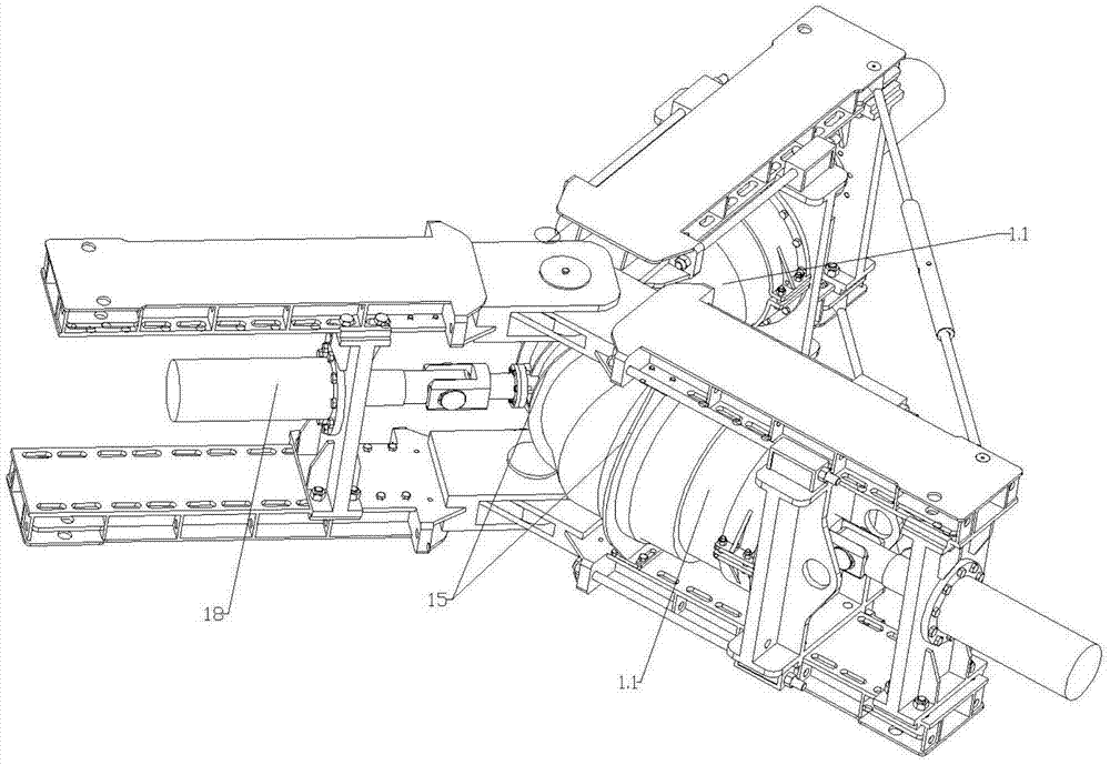
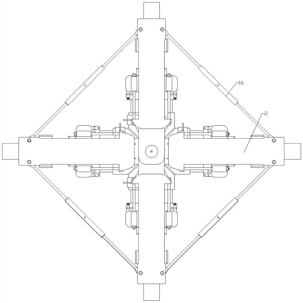
[0026] As shown in the figure, the general-purpose steel-plastic composite pipe piston pressure test device of the present invention includes an upper beam 2 arranged above each pipe section 1.1 of the steel-plastic composite pipe 1 and a lower beam arranged below each pipe section 1.1 of the steel-plastic composite pipe 1 3. Plugging the ports 1.1 of each pipe section 1 of the steel-plastic composite pipe 1 to achieve zero leakage. Institutions, and the industry is accustomed to call the piston pressure test mechanism. The upper beam 2 is hinged on the same upper fulcrum, and the lower beam 3 is hinged on the same lower fulcrum.

[0027] The number of upper beams and lower beams can be set according to the number of steel-plastic composite pipe sections: for straight-line pipes, two upper beams with an included angle of 180 degrees and two lower beams with ...


PUM


Abstract

A general-purpose steel-plastic composite pipe piston-type pressure test device, including an upper beam and a lower beam, and a piston-type pressure-test mechanism for sealing the ports of each pipe section of the steel-plastic composite pipe to achieve zero leakage. The piston-type pressure test mechanism includes an upper and lower The beam is connected and tightly pressed on the baffle at the end of the pipe section, the clamp installed on the baffle and tightly sleeved on the pipe section, the piston and the retaining ring, the sealing ring, the water inlet is provided and the head passes through the baffle and the middle section is limited. The push-pull head on the baffle, the water inlet connecting pipe and the oil cylinder that are sealed and connected to the piston and the head of the push-pull head at both ends, and connected to the water inlet, the upper beam is hinged on the same upper fulcrum, and the lower beam is hinged on the same lower fulcrum On the top, the end of the push-pull head is provided with a strip-shaped hole for the pin shaft installed on the free end of the piston rod of the oil cylinder to move back and forth, and the distance that the strip-shaped hole can move relative to the pin shaft is greater than the compression amount of the sealing ring. The pressure test device can be used for pressure test of various types of steel-plastic composite pipes, can be installed in an integrated manner, and has no leakage during the pressure test.

Description

technical field [0001] The invention relates to the technical field of pressure testing of steel-plastic composite pipes, in particular to a general-purpose piston-type pressure testing device for steel-plastic composite pipes. Background technique [0002] In the production process of steel-plastic composite pipes (including pipes, pipe fittings, etc.), it is necessary to test the short-term hydrostatic strength and burst strength of the pipe body to detect the physical and mechanical properties and ultimate pressure of the pipe body, so as to adjust the steel-plastic composite pipe in time. The steel skeleton structure in the composite pipe enables the produced products to meet the standard requirements. [0003] CN2565012Y shows a special pressure test tool for steel-plastic composite pipes. During the pressure test, as the test hydraulic pressure gradually increases, when the axial force borne by the lining core exceeds the pressure block and the pipe outer When the bit...

Claims


Application Information

Patent Timeline
Patent Type & Authority Patents(China)
IPC IPC(8): G01N3/12
Inventor 陈建匀刘洪李毅芳钟秋明邓源财徐洲
Owner 安源管道实业股份有限公司
Why Eureka
Try Eureka