Battery pack

A technology for battery packs and battery units, which is applied to battery pack components, circuits, electrical components, etc., and can solve problems such as separation of upper and lower covers, inconvenient production rework, and no effective combination

Active Publication Date: 2015-10-14
SKYBEST ELECTRIC APPLIANCE SUZHOU CO LTD
View PDF3 Cites 6 Cited by
  • Summary
  • Abstract
  • Description
  • Claims
  • Application Information

AI Technical Summary

Problems solved by technology

However, it is inconvenient to disassemble the cell assembly when the foam sticks to it, which will bring inconvenience to large-scale production rework
At the same time, the method of using foam does not effectively combine the upper cover and the lower cover group into a whole
If the structure connecting the upper cover and the lower cover (such as screw and screw post structure) is relatively fragile or the cell assembly itself increases in size and weight, it is still easy to cause dislocation of the connection between the upper and lower covers and the separation of the upper and lower covers

Method used


Image

  • Battery pack
  • Battery pack
  • Battery pack

Examples


Embodiment Construction

[0020]

[0021] The present invention will be further described below in conjunction with the accompanying drawings.

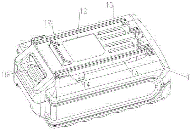
[0022] refer to figure 1 The battery pack shown has a casing 1 which is roughly in the shape of a cuboid. A square joint 12 protruding outward is provided on the upper surface of the battery pack, and slide grooves 13 are provided on both sides of the joint. The chute is used to slide at the position where the battery pack of the electric tool is installed, and the corresponding electric tool has a bracket structure (not shown in the figure) that cooperates with the chute. An elastic ejector 14 is provided at the end of the chute, and the elastic ejector is used to provide an auxiliary ejection function when taking out the battery. An electrode groove 15 is provided at the front end of the joint part 12, and the charging electrode and the discharging electrode of the battery pack are built in the electrode groove 15. When the electric tool and the battery p...


PUM


Abstract

The invention relates to a battery pack which comprises a shell, a battery core assembly and electrodes, wherein the shell is formed by combining an upper cover and a lower cover; the battery core assembly comprises at least one battery unit and a bracket which is used for containing the at least one battery unit. The battery pack is characterized in that a columnar opposite-inserting structure is arranged among the bracket, the upper cover and the lower cover; the columnar opposite-inserting structure comprises limiting columns and limiting holes; during assembling, the limiting columns are inserted into the limiting holes. As the limiting columns of the opposite-inserting structure on the at least one battery unit are combined with the limiting holes of the upper cover and the lower cover of the battery pack, the battery core assembly and the shell are kept in a good integrality; the inserted limiting columns on the battery unit bracket can deform at the moment that the battery pack falls down, and the impact of the battery core assembly on the shell can be buffered during falling down, so that the connection malposition of the upper cover and the lower cover of the shell can be prevented during falling down and further the shell can not be separated.

Description

technical field [0001] The invention relates to a battery pack. Background technique [0002] Battery packs are commonly used components of electric tools, such as garden tools, such as electric lawn trimmers, electric blowers, and electric chain saws. For extended operating time, the battery pack is a replaceable separate component. The battery pack stores a lot of energy and has a high energy density. For safety, the battery pack usually has a certain drop resistance. Existing battery packs are usually composed of cell components, battery pack upper cover, battery pack lower cover and other components. Due to machining accuracy errors and assembly requirements, when the assembly of the cell assembly and the upper and lower covers of the battery pack is completed, there is a fit gap between the shell formed by the upper cover and the lower cover of the battery pack and the cell assembly, and the shell cannot fully align with the battery pack. Core assembly positioning. ...

Claims


Application Information

Patent Timeline
Patent Type & Authority Applications(China)
IPC IPC(8): H01M2/10H01M50/242H01M50/244H01M50/291
CPCY02E60/10
Inventor 徐悦龙张天才卞小贤刘文杰
Owner SKYBEST ELECTRIC APPLIANCE SUZHOU CO LTD
Why Eureka
Try Eureka