Image reading device and phase difference correction method for image reading device

A technology of image reading equipment and correction method, which is applied in the direction of image communication, electrical components, etc., can solve the problem that the phase difference of the sampling clock signal CDSCLK is not easy to determine, and achieve the effect of solving the problem that the phase difference is not easy to determine

Active Publication Date: 2018-07-03
SHANDONG NEW BEIYANG INFORMATION TECH CO LTD
View PDF5 Cites 0 Cited by
  • Summary
  • Abstract
  • Description
  • Claims
  • Application Information

AI Technical Summary

Problems solved by technology

[0007] The main purpose of the present invention is to provide an image reading device and a phase difference correction method for the image reading device to solve the image processing time point clock signal CLK and sampling clock signal existing in the image reading device in the prior art The problem that the phase difference of CDSCLK is not easy to determine

Method used


Image

  • Image reading device and phase difference correction method for image reading device
  • Image reading device and phase difference correction method for image reading device
  • Image reading device and phase difference correction method for image reading device

Examples


Embodiment Construction

[0031] It should be noted that, in the case of no conflict, the embodiments in the present application and the features in the embodiments can be combined with each other. The present invention will be described in detail below with reference to the accompanying drawings and examples.

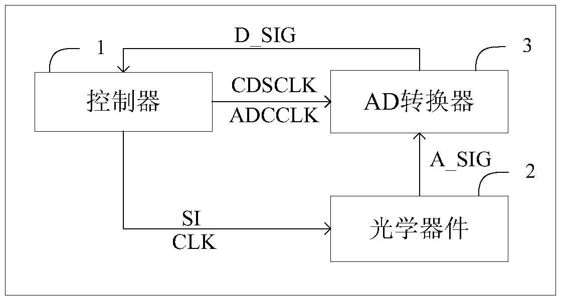
[0032] image 3 is a schematic diagram of the module composition of the image reading device according to the first embodiment of the present invention, such as image 3 As shown, the image reading apparatus 100 includes a CPU 10 , a communication interface 11 , an FPGA (Field Programmable Gate Array) 12 , an optical device 13 , an AD converter 14 , a memory 15 , and an indicator 16 .

[0033] CPU10 is used to control other modules to perform work. For example, CPU10 controls the application program loading of FPGA12 so that FPGA12 can work normally. data transmission, the CPU 10 controls the memory 15 to store data, etc.

[0034] The communication unit 11 is configured to perform data trans...


PUM


Abstract

The invention discloses an image reading device and a phase difference correction method for the image reading device. The image reading device includes an optical device and an AD converter. The optical device is used to collect the optical image of the scanned medium when the dot clock signal CLK is valid to obtain an analog image signal. Sampling the image signal and performing analog-to-digital conversion on the sampled signal to obtain digital image data. The phase difference correction method includes: obtaining the phase difference of the dot clock signal CLK and the sampling clock signal CDSCLK when the phase difference of the sampling clock signal CDSCLK is sequentially set to a plurality of preset values. Outputting a plurality of digital image data; determining a corrected phase difference from the plurality of digital image data. The present invention solves the problem that the phase difference between the clock signal CLK and the sampling clock signal CDSCLK at the time point of image processing is difficult to determine in the image reading device in the prior art.

Description

technical field [0001] The present invention relates to the field of image processing, in particular to an image reading device and a phase difference correction method for the image reading device. Background technique [0002] With the development of paperless office, image reading devices such as scanners and facsimile machines are widely used. Device (CCD for short) or contact image sensor (Contact Image Sensor, CIS for short). The analog image signal is output to the AD converter, and the AD converter performs AD conversion to generate a digital image signal, and the image reading device uploads the digital image signal to the computer. [0003] figure 1 It is a schematic diagram of the module composition of an image reading device in the prior art. As shown in the figure, the image reading device includes a processor 1, an optical device 2, and an AD converter 3, and the processor 1 outputs to the optical device 2 and the AD converter 3 Control signals, wherein the ...

Claims


Application Information

Patent Timeline
Patent Type & Authority Patents(China)
IPC IPC(8): H04N1/00H04N1/047
Inventor 王波涛邢燕斌张诗水董述恂
Owner SHANDONG NEW BEIYANG INFORMATION TECH CO LTD
Why Eureka
Try Eureka