Sliding-type induction material receiving device

A collection device, sliding technology, applied in the direction of sliding fastener elements, applications, fasteners, etc., can solve the problems of difficulty in determining the startup time of the collection device, and the zipper is not easy to remove, so as to save automatic material collection, save manpower, The effect of easy replacement

Pending Publication Date: 2017-05-10
ANHUI HUALIDA ZIPPER
View PDF4 Cites 0 Cited by
  • Summary
  • Abstract
  • Description
  • Claims
  • Application Information

AI Technical Summary

Problems solved by technology

[0004] In order to solve the above technical problems, we propose a sliding induction receiving device, which solves the difficulty in determining the starting time of the collecting device due to the difference in production speed in ordinary zipper collecting devices and the difficulty in determining the collected whole bundle of zippers from the rotating shaft. The removed problem achieves the goal of saving manpower and automatically receiving materials

Method used


Image

  • Sliding-type induction material receiving device

Examples


Embodiment

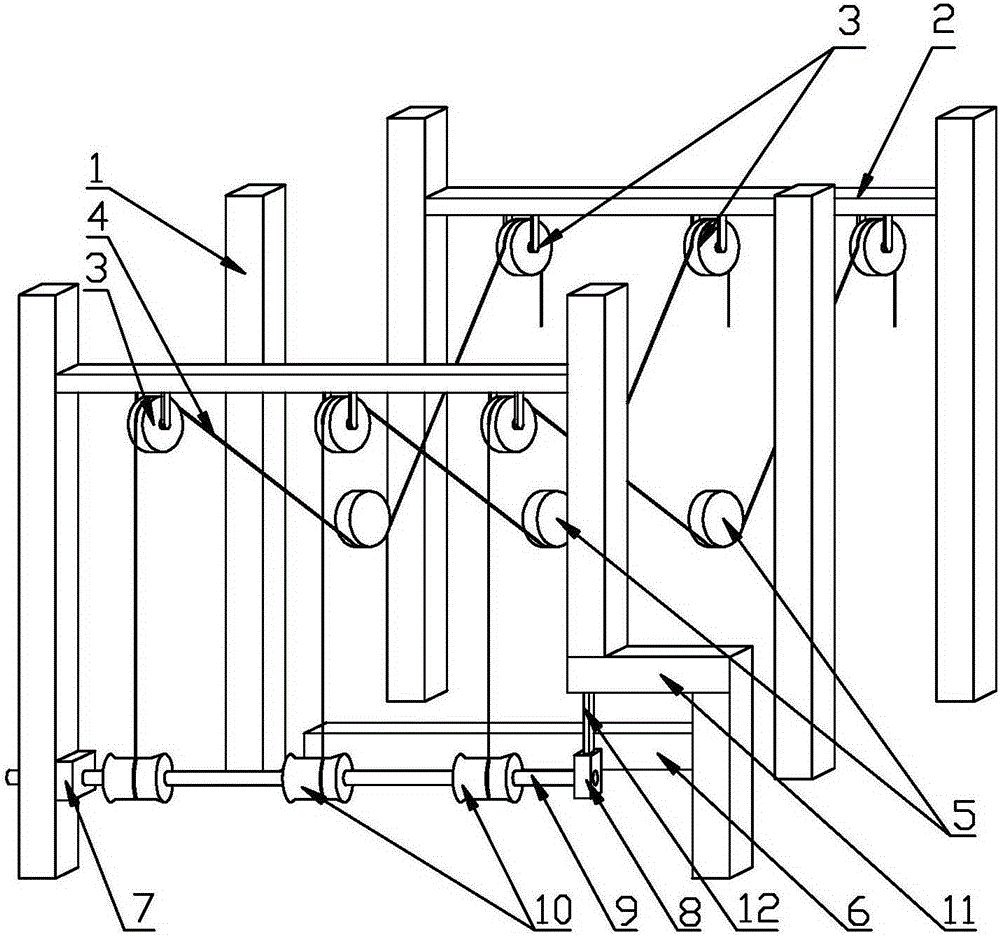
[0026] Such as figure 1 As shown, a sliding induction receiving device includes a frame 1 and an induction touch device and a zipper collection device arranged on the frame 1. The induction touch device includes two laterally fixed The fixed rods 2 on the front and rear sides, the fixed pulley 3 fixed on the bottom of each fixed rod 2 in groups, and the movable pulley 5 that moves up and down in the middle of every two fixed pulleys 3 through the zipper 4 that needs to be transmitted, the two The fixed pulley 3 and a moving pulley 5 form a receiving group, the outer circumference of the fixed pulley 3 and the moving pulley 5 have the same structure and grooves, and the grooves match the structure of the slide fastener 4 bypassing the grooves. An inductor 6 is fixedly installed in the frame 1, and the inductor 6 is located directly below the movable pulley 5;

[0027] The zipper collecting device includes a mounting seat 7 arranged on one side of the bottom of the frame 1, a m...


PUM


Abstract

The invention discloses a sliding-type induction material receiving device. The sliding-type induction material receiving device comprises a rack as well as an induction triggering device and a zipper collecting device which are arranged on the rack, wherein the induction triggering device comprises two fixing rods horizontally and fixedly arranged on the front side and rear side of the top of the rack, a plurality of groups of fixed pulleys fixed to the bottom of each fixing rod, and movable pulleys movably arranged between the fixed pulleys and being capable of moving vertically through zippers needing to be conveyed, an inductor is fixedly mounted in the rack, and the zipper collecting device comprises a mounting base I arranged at one side of the bottom of the rack, a mounting base II arranged at the other side of the bottom of the rack, and a rotation shaft clamped between the mounting base I and the mounting base II. According to the sliding-type induction material receiving device, through the induction triggering device connected with a material receiving starting device arranged a zipper stacking part, the problems that in the common zipper collecting device, due to the differences of the production speeds, the starting time of the collecting device is difficult to determine, and the collected bundled zippers can not be taken down from the rotation shaft easily are solved.

Description

technical field [0001] The invention relates to the field of zipper production equipment, in particular to a sliding induction receiving device. Background technique [0002] Zipper is a connecting piece that relies on the continuous arrangement of chain teeth to make items merge or separate. It is now widely used in clothing, bags, tents, etc. It is a fastener composed of two belts with a row of metal teeth or plastic teeth. Used to connect the edges of an opening, having a slider that pulls two rows of teeth into an interlocking position to close the opening; a chain attached to something to tension, stabilize, or guide that thing. Zipper equipment can be divided into tooth setting machine, polishing machine, ironing machine, bottom stop machine, slider machine, top stop machine and chain shearing machine according to the production process. [0003] From one process to another in the production process, in order to ensure that the program is compact and orderly without c...

Claims


Application Information

Patent Timeline
Patent Type & Authority Applications(China)
IPC IPC(8): A44B19/42
Inventor 戎伟王东宝王文忠孙雪莉
Owner ANHUI HUALIDA ZIPPER
Why Eureka
Try Eureka