Multifunctional LED light modulation interface circuit

A dimming interface and multi-functional technology, applied in the field of multi-functional LED dimming interface circuit, can solve the problems of poor linearity, high cost, long development cycle, etc., and achieve the effect of low cost, good linearity and flexible setting

Active Publication Date: 2015-10-14
SHANGHAI ARCATA ELECTRONICS
View PDF4 Cites 10 Cited by
  • Summary
  • Abstract
  • Description
  • Claims
  • Application Information

AI Technical Summary

Problems solved by technology

At present, it is difficult for the dimming interface circuit to be compatible with multiple dimming control signals on the same interface, and users are often required to connect to different ports according to the type of dimming control signals, which brings troubles to terminal application customers.
In addition, in the existing implementation schemes, single-chip

Method used


Image

  • Multifunctional LED light modulation interface circuit
  • Multifunctional LED light modulation interface circuit
  • Multifunctional LED light modulation interface circuit

Examples


Embodiment Construction

[0024] The invention is a multifunctional LED dimming interface circuit, the same interface circuit is compatible with multiple dimming control modes, and has the characteristics of flexible dimming interval setting and good linearity.

[0025] Referring to the accompanying drawings, the present invention will be further described.

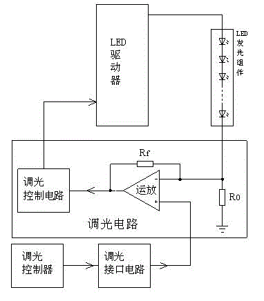
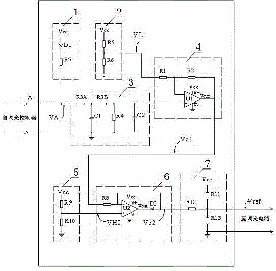
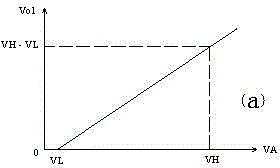
[0026] Such as figure 2 As shown, the multifunctional LED dimming interface circuit consists of a power supply circuit (1), a dimming interval lower limit setting circuit (2), a filter circuit (3), a subtractor (4), a dimming interval upper limit setting circuit (5), A limiter (6) and a weighted addition circuit (7), the input end of the dimming interface circuit is A, and the feature is that the power supply circuit (1) and the filter circuit (3) are connected to the input end A, and the filter circuit ( 3) output to one input terminal of the subtractor (4), and subtract the dimming interval lower limit setting voltage of the dimming interval l...


PUM


Abstract

A multifunctional LED light modulation interface circuit includes a power supply circuit, a light modulation zone lower limit setting circuit, a filter circuit, a subtracter, a light modulation zone upper limit setting circuit, an amplitude limiter and a weighted addition circuit. The power supply circuit and the filter circuit are connected on the input end of an interface circuit. The power supply circuit supplies DC voltage to a resistance-variable light modulator and the filter circuit filters control signals when pulse-width modulation control signals are input, and the output of the filter circuit is subtracted by voltage of the light modulation zone lower limit setting circuit in the subtracter. After the lowest level is limited, the output of the subtracter and the light modulation zone upper limit setting voltage set the highest level in an amplitude limiting circuit. The weighted addition circuit output weighted linear change and light modulation referential voltage with high and low level limits according to the requirement of a modulated light brightness variation scope. The interface circuit is compatible with a plurality of light modulation control means. The multifunctional LED light modulation interface circuit is low in cost, flexible in light modulation zone setting, and excellent in linearity.

Description

technical field [0001] The invention relates to dimming control of a dimmable LED driver, in particular to a multifunctional LED dimming interface circuit. Background technique [0002] In recent years, LED lighting has shown a rapid development trend due to its advantages such as high energy efficiency, long life, small size, and environmental protection. Especially in the field of dimming applications, it also has continuously adjustable brightness, fast dimming speed, dimming The advantages of low light depth, high dimming precision and easy digital control have been widely used. [0003] Since the volt-ampere characteristics of LEDs present nonlinear and negative temperature characteristics, constant current driving is generally used in LED lighting. By continuously changing the magnitude of the LED current, the purpose of dimming can be achieved. This dimming method is also called analog dimming. During analog dimming, the working current of the LED is continuous and ...

Claims


Application Information

Patent Timeline
IPC IPC(8): H05B37/02
Inventor 张顺法
Owner SHANGHAI ARCATA ELECTRONICS
Why Eureka
Try Eureka