Stirring device

A stirring device and stirring shaft technology, which is applied to clay stirring devices, cement stirring devices, mixers with rotating stirring devices, etc., can solve problems such as poor mixing uniformity, achieve uniform water injection, increase rotation speed, and shorten mixing time Effect

Active Publication Date: 2015-10-21
ZHANJIANG JIANKE ENG QUALITY TESTING CENT CO LTD
View PDF7 Cites 12 Cited by
  • Summary
  • Abstract
  • Description
  • Claims
  • Application Information

AI Technical Summary

Problems solved by technology

[0004] For this reason, the technical problem to be solved by the present invention is to overcome the problem of poor stirring uniformity of the stirring device in the prior art, thereby proposing a stirring device that can greatly improve the stirring uniformity

Method used


Image

  • Stirring device
  • Stirring device
  • Stirring device

Examples


Embodiment Construction

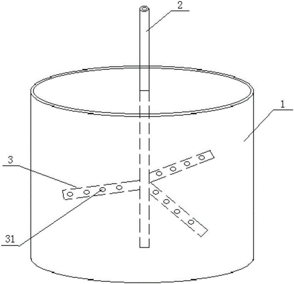
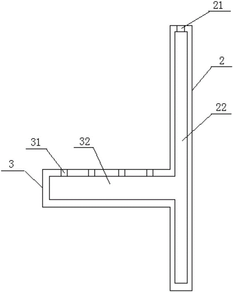
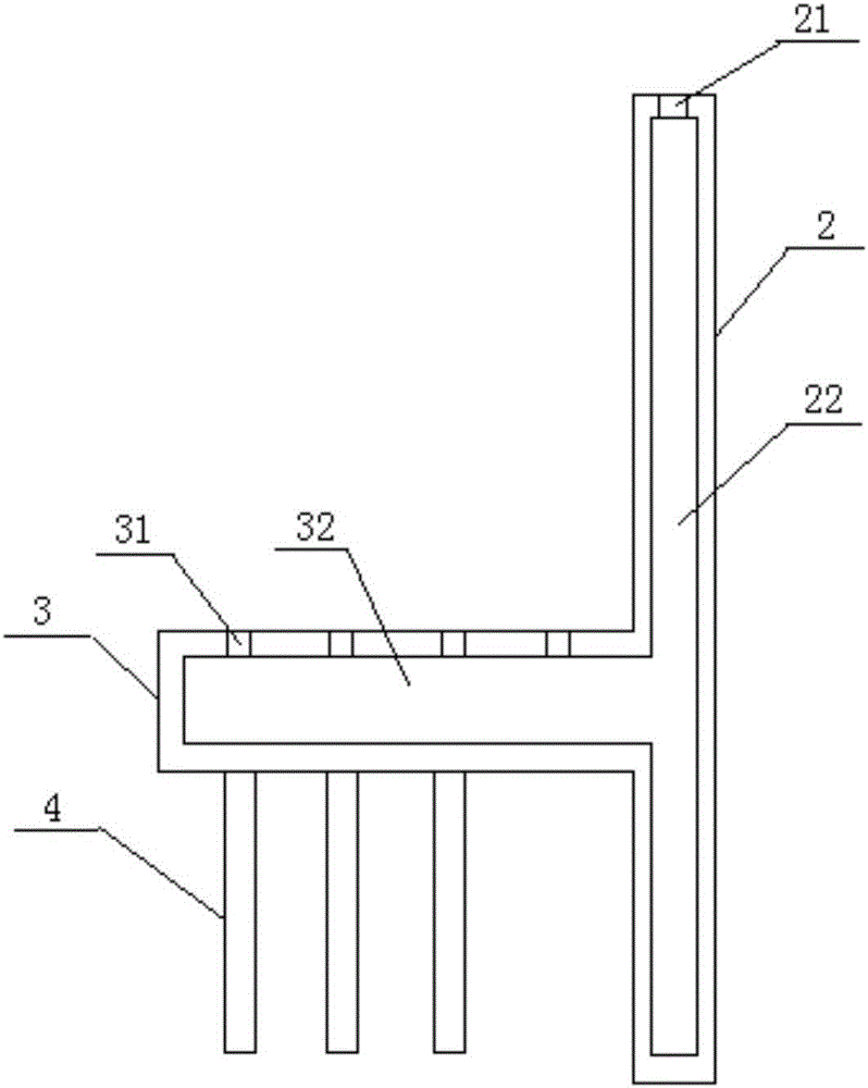
[0031] refer to figure 1 , is a structural schematic diagram of an embodiment of a stirring device, which includes a box 1 with an open upper end, a stirring shaft 2 and a stirring paddle 3 . figure 2 A cross-sectional view showing the stirring shaft and paddle, as figure 2 As shown, the stirring shaft 2 is connected to the stirring paddle 3, the stirring shaft 2 includes a first hollow cavity 22, and the wall of the first hollow cavity 22 is provided with a water injection port 21; the stirring paddle 3 includes a second hollow cavity 32, The second hollow body 32 communicates with the first hollow body 22 , and a plurality of first water outlet holes 31 are opened on the wall of the second hollow body 32 .

[0032] When stirring, fluid substances such as water are injected from the water injection port 21 , flow through the first hollow cavity 22 , flow into the second hollow cavity 32 , and then flow out from the plurality of first water outlet holes 31 .

[0033] In th...


PUM


Abstract

The invention discloses a stirring device. The stirring device comprises a box body with an opening in the upper end, a stirring shaft and a stirring paddle, wherein the stirring shaft is connected with the stirring paddle, the stirring shaft comprises a first hollow cavity, and a water injection port is formed in the cavity wall of the first hollow cavity; the stirring paddle comprises a second hollow cavity, the second hollow cavity is communicated with the first hollow cavity, and a plurality of water outlet holes are formed in the cavity wall of the second hollow cavity. The stirring device disclosed by the invention can greatly improve the stirring uniformity.

Description

technical field [0001] The invention relates to the technical field of stirring device design, in particular to a stirring device. Background technique [0002] Stirring devices are commonly used in civil engineering to stir raw materials such as soil, cement, sand and gravel. Usually, when stirring these raw materials, fluid substances such as water need to be injected into them, so that the raw materials are evenly stirred into a paste or fully mixed. Soggy. [0003] At present, there are some designs of stirring devices. For example, there is a stirrer, which includes a stirring shaft and a stirring paddle, wherein the stirring shaft is a hollow shaft with through holes distributed on the shaft wall, and the stirring shaft is connected with a water injection pipe. When the mixer is working, the water flows into the stirring shaft through the water injection pipe, and flows out through the through holes distributed on the shaft wall of the stirring shaft, so as to achieve...

Claims


Application Information

Patent Timeline
Patent Type & Authority Applications(China)
IPC IPC(8): B01F7/18B28C5/16B28C7/12B28C3/00
Inventor 李鹏王加民马伟诚袁爱国周海斌荆亚韡
Owner ZHANJIANG JIANKE ENG QUALITY TESTING CENT CO LTD
Why Eureka
Try Eureka