Friction-stir welding equipment

A technology of friction stir welding and equipment, which is applied in welding equipment, non-electric welding equipment, metal processing equipment, etc., can solve the problems of restricting the application of friction stir welding technology, increasing the production cost of enterprises, and scrapping the stirring head, so as to promote comprehensive promotion and Large-scale application, reduction of torsional or impact force, material and cost saving effects

Active Publication Date: 2015-10-21
重庆派馨特机电有限公司
View PDF8 Cites 21 Cited by
  • Summary
  • Abstract
  • Description
  • Claims
  • Application Information

AI Technical Summary

Problems solved by technology

[0003] In the actual friction stir welding process, the friction stir welding equipment used in the industry often adopts a fixed worktable, and realizes the welding between metals through the movement of the X-axis, Y-axis and other directions of the stirring head, so that the equipment volume is relatively small. Huge and bulky, resulting in high equipment production costs, which greatly limits the application of friction stir welding technology in the civil industry, and

Method used


Image

  • Friction-stir welding equipment
  • Friction-stir welding equipment
  • Friction-stir welding equipment

Examples


Example Embodiment

[0064] The following specific examples illustrate the implementation of the invention. Those familiar with this technology can easily understand other advantages and effects of the invention from the content disclosed in this specification.
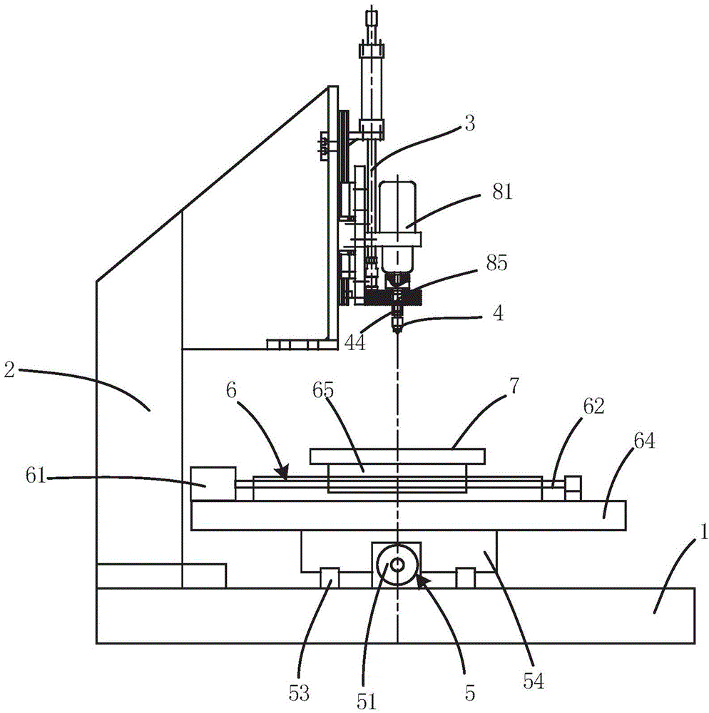
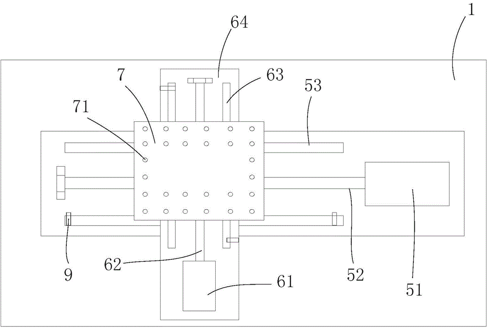
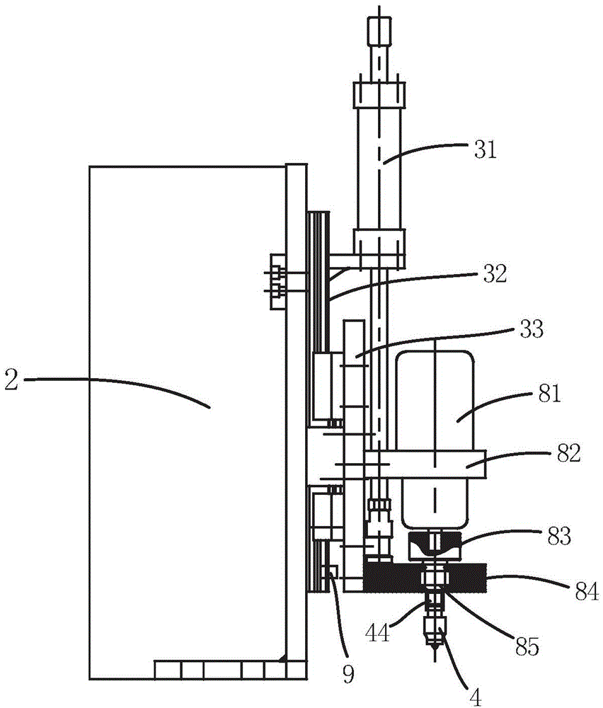
[0065] Such as Figure 1 to Figure 3 As shown, the present invention provides a friction stir welding equipment, including a machine tool body for friction stir welding, a stirring head is installed on the main shaft of the machine tool body, a floating support structure is provided between the stirring head and the main shaft, and the floating support structure It includes a connecting part 44 and an elastic support. The connecting part 44 is fixed to the main shaft. The lower part of the connecting part 44 and the upper part of the mixing head are matched by a plurality of concave and convex parts, and can be rotated synchronously. The elastic support rests on the lower end of the connecting part 44 and the mixing head. Between the upper en...


PUM


Abstract

The invention provides friction-stir welding equipment. The friction-stir welding equipment comprises a machine tool body for friction-stir welding. A stir head is installed on a spindle of the machine tool body. A floating supporting structure is arranged between the stir head and the spindle and comprises a connecting component and an elastic supporting piece. The connecting component is fixed to the spindle, the lower portion of the connecting component and the upper portion of the stir head are matched through a plurality of concave parts and convex parts, and the connecting component and the stir head can rotate synchronously. The elastic supporting piece is arranged between the lower end of the connecting component and the upper end of the stir head in an abutting mode. A limiting structure is arranged on the connecting component and used for preventing the stir head from disengaging from the lower end of the connecting component. The friction-stir welding equipment can keep pressure constant in welding and improve the quality of welded joints. When disturbance or other accidents occur, torsion or impact force on the stir head can be reduced, so that the stir head is easy to protect and not prone to fracture, and the service life of the stir head is prolonged. The structure of the spindle is simplified, so that the whole equipment has a light weight and a small size, materials are saved, and cost is lowered.

Description

technical field [0001] The invention relates to the field of friction stir welding equipment, in particular to a friction stir welding equipment. Background technique [0002] Friction stir welding is an invention patent proposed by the British Welding Institute in October 1991. The friction stir welding process was originally mainly used to solve the welding of low melting point materials such as aluminum alloys. As an advanced solid-phase joining technology, friction stir welding is widely used in aerospace, rail transit, national defense and military industry, ships and automobiles and other fields. In the process of friction stir welding, a stirring head is used to insert the part to be welded of the workpiece, and through the friction stirring between the stirring head and the workpiece, the friction heat makes the metal in this part in a thermoplastic state and is plasticized from the front end to the rear under the pressure of the stirring head flow, so that the par...

Claims


Application Information

Patent Timeline
IPC IPC(8): B23K20/12
CPCB23K20/1245
Inventor 唐远金陈康李力杜彦斌黄木春赵学渝
Owner 重庆派馨特机电有限公司
Why Eureka
Try Eureka