Welding tool with cooling structure

A welding fixture and cooling structure technology, applied in the field of fixtures, can solve problems such as low welding efficiency and poor welding quality, and achieve the effects of reducing reprocessing rate, improving welding efficiency, and reasonable structural design

Active Publication Date: 2015-10-21
江苏欧力佳电子科技有限公司
View PDF5 Cites 17 Cited by
  • Summary
  • Abstract
  • Description
  • Claims
  • Application Information

AI Technical Summary

Problems solved by technology

At present, manual welding is mainly used. Due to the lack of supporting fixtures, the welding efficiency is extremely low, and the welding quality is not good

Method used


Image

  • Welding tool with cooling structure
  • Welding tool with cooling structure
  • Welding tool with cooling structure

Examples


Embodiment Construction

[0031] The specific embodiments of the present invention will be further described below in conjunction with the accompanying drawings.

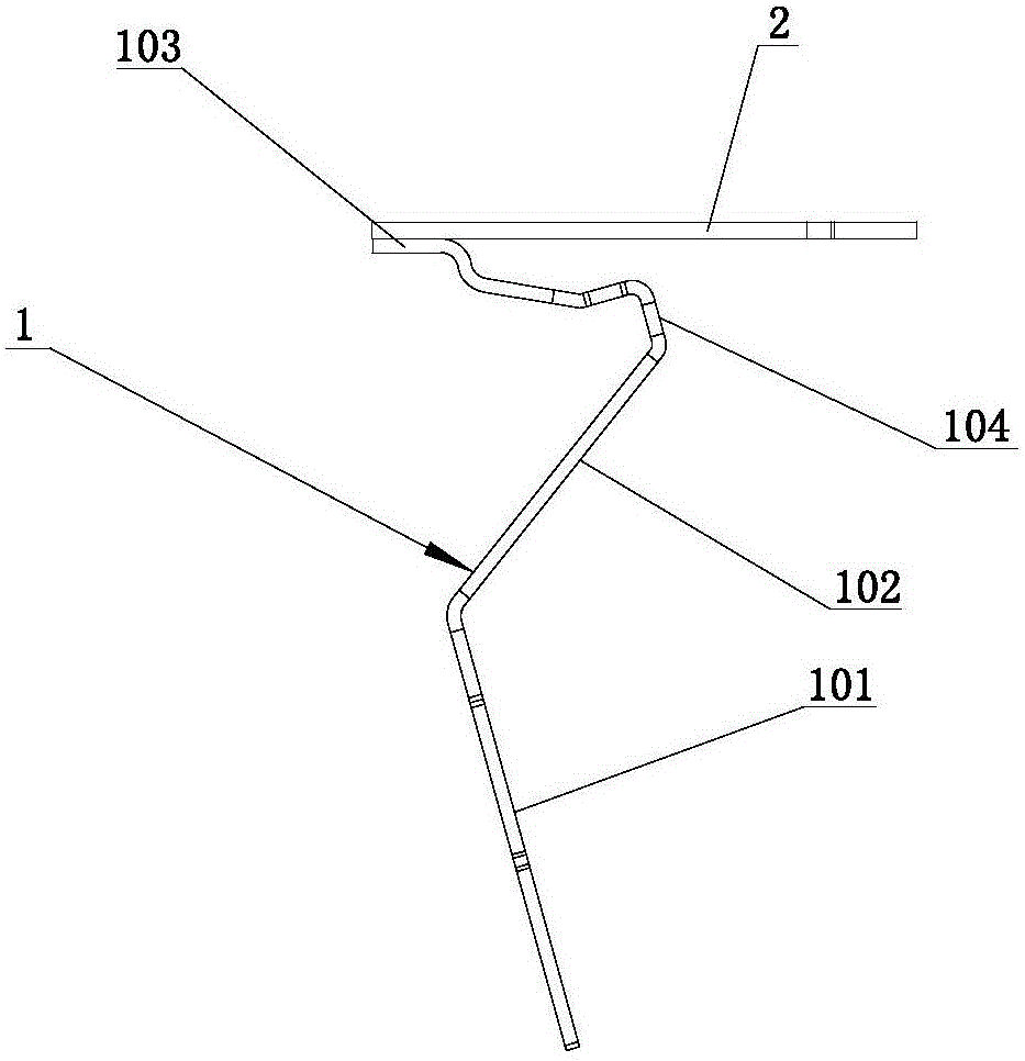
[0032] Such as figure 1 As mentioned above, in the welding jig with cooling structure of this embodiment, the arc bending plate 1 includes a lower folded part 101, an upper folded part 102 and a welded part 103, and a bent part 104 is provided between the upper folded part 102 and the welded part 103. , the welding portion 103 is welded to the horizontal horizontal plate 2 .

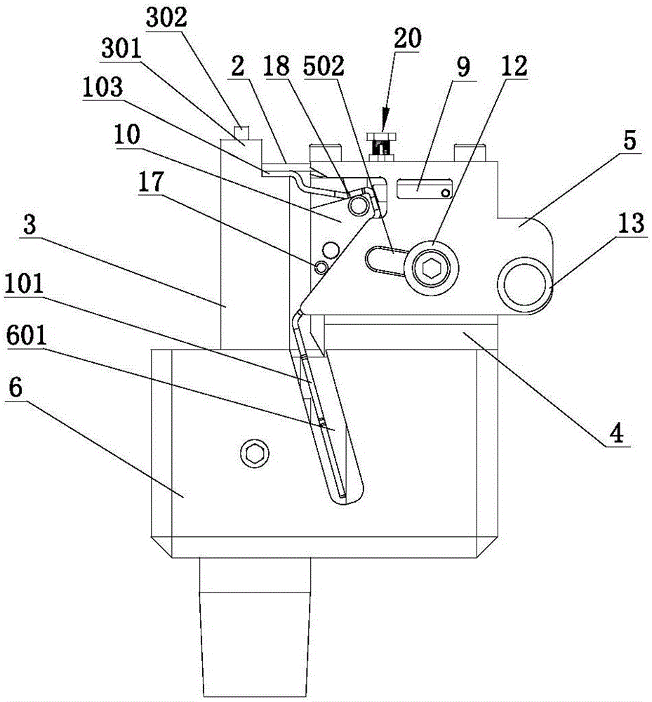
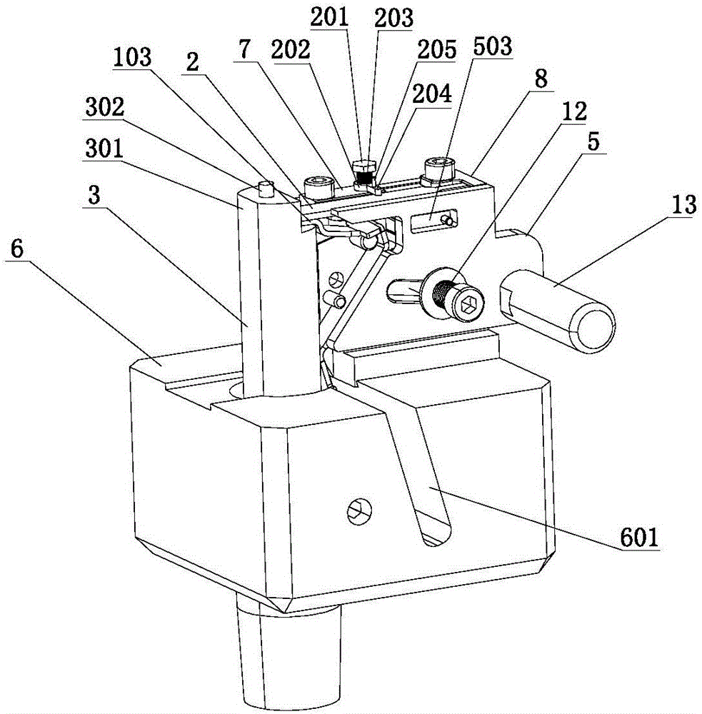
[0033] Such as figure 2 , image 3 and Figure 4 As described, the welding positioning tool of the present invention includes a base 6, on which a welding support column 3 and a welding seat 4 are installed, and a side splint 5 is installed on the side of the welding seat 4, and a first positioning plate 7 and a second positioning plate 7 are installed on the upper end thereof. Two positioning plates 8, the horizontal horizontal plate 2 is longitudinally clamped b...


PUM


Abstract

The invention relates to a welding tool with a cooling structure. The welding tool comprises a pedestal; a welding support column and a welding seat are installed on the pedestal. A side clamp plate is installed at the side of the welding seat; a first positioning plate and a second positioning plate are installed on the upper end surface; a horizontal transverse plate is clamped longitudinally between the first positioning plate and the side clamp plate; and the horizontal position of the horizontal transverse plate is limited by the second positioning plate. Besides, a placing groove for placing a lower folding part of a bending arc plate is formed in the pedestal; clamping space for clamping the upper folding part is formed between the welding seat and the side surface of the welding support column; and the welding part of the bending arc plate is placed on the upper end surface of the welding support column horizontally and is in contact with the horizontal transverse plate. An elastic positioning structure is installed between the side clamp plate and the welding seat and includes an abutting pressing plate; one end of the abutting pressing plate is abutted against the bending folding part of the bending arc plate; an end spring is installed between the other end of the abutting pressing plate and the welding seat; and the end portion of the end spring is abutted against a fixed shot column of the welding seat.

Description

technical field [0001] The invention relates to the technical field of tooling fixtures, in particular to a welding tooling for arc-bending plates. Background technique [0002] The structure of curved arc plate 1 is as follows figure 1 As mentioned above, it needs to be welded with the horizontal plate 2. The curved arc plate 1 is formed by bending, including the lower folded part 11, the upper folded part 12 and the welded part 13 from bottom to top. There is a bending part 14 between them, and the welding place of the welding part 13 is a flat plate structure, and is surface welded with the horizontal plate 2 . At present, manual welding is mainly used. Due to the lack of supporting fixtures, the welding efficiency is extremely low, and the welding quality is not good. Contents of the invention [0003] In view of the above-mentioned shortcomings of the prior art, the applicant has researched and designed a welding jig with a cooling structure, which can clamp and fix...

Claims


Application Information

Patent Timeline
Patent Type & Authority Applications(China)
IPC IPC(8): B23K37/04
CPCB23K37/003B23K37/0443
Inventor 王琼琦
Owner 江苏欧力佳电子科技有限公司
Why Eureka
Try Eureka