
Supporting rotating table for mechanical machining of thin-wall workpiece

A technology of mechanical processing and support table, which is applied in the direction of metal processing machinery parts, metal processing equipment, supports, etc., can solve the problems of affecting the processing accuracy of workpieces, high workpiece scrap rate, and increasing manufacturing costs, so as to improve clamping accuracy and ensure The effect of pressure magnitude and improvement of driving accuracy

Active Publication Date: 2015-10-21
ANHUI SCI & TECH UNIV
View PDF6 Cites 15 Cited by
  • Summary
  • Abstract
  • Description
  • Claims
  • Application Information

AI Technical Summary

Problems solved by technology

[0002] In mechanical processing production, it is generally necessary to process various angles of the workpiece according to different production requirements. At present, in mechanical processing, the rotation and positioning of the workpiece are generally achieved by manual flipping or rotation, or only The motor is used to directly drive the turntable to rotate. However, in terms of the rotation angle of the turntable, it is difficult to achieve accurate rotation of the workpiece angle, and deviation is easy to occur. Once the rotation deflection angle is large, it will affect the machining accuracy of the workpiece. Especially for the processing of thin-walled workpieces, since the rigidity of the workpiece is relatively fragile, using this manual adjustment method will easily cause damage to the workpiece when it is clamped multiple times, resulting in a high scrap rate of the workpiece. large, which increases the manufacturing cost. Moreover, the current turntable generally only clamps and fixes the workpiece by pressing or pushing. This method cannot realize the clamping and processing of thin-walled fragile parts. The processing turntable for thin-walled workpieces can increase the rotation angle of the turntable and improve the clamping efficiency of thin-walled workpieces, which is a technical problem that people have always hoped to solve

Method used


Image

  • Supporting rotating table for mechanical machining of thin-wall workpiece

Examples


Embodiment Construction

[0017] The present invention will be described in detail below in conjunction with the accompanying drawings. However, it should be understood that the accompanying drawings are provided only for better understanding of the present invention, and they should not be construed as limiting the present invention.

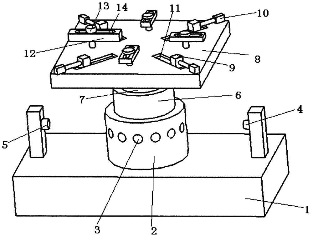
[0018] Such as figure 1 As shown, the present invention provides a support turntable for machining thin-walled workpieces, which includes a base 1, a turntable 2, a through hole 3, a light emitter 4, a light receiver 5, a support table 8, a top plate 9 and a pressure plate 12, The turntable 2 is rotatably arranged on the base 1, and the turntable 2 is driven to rotate by a motor arranged inside the turntable. A plurality of said through holes 3 are uniformly arrayed on the side wall of the turntable 2, and one end of the base 1 is provided with The light transmitter 4, the other end of the base 1 is provided with a light receiver 5, and the straight line between the li...


PUM

PropertyMeasurementUnit
Diameteraaaaaaaaaa

Abstract

The invention provides a supporting rotating table for mechanical machining of a thin-wall workpiece. A rotating table is rotatably arranged on a base, and is driven by a motor arranged in the rotating table to rotate; a plurality of through holes are evenly arranged on the side wall of the rotating table in an array manner; a light emitter is arranged at one end of the base, and a light receiver is arranged at the other end of the base; the straight line between the light emitter and the light receiver right just penetrates the radial circle centre of the rotating table so that the light receiver can receive light which is emitted by the light emitter and passes through the through holes; and the light receiver is connected with the motor inside the rotating table, and is used for controlling starting and stopping of the motor. Through the supporting rotating table, the light emitted by the light emitter penetrates the through holes, so that the light receiver controls and drives starting and stopping of the motor of the rotating table according to the magnitude of the received light, and the driving precision of the angle can be greatly improved; and the pressure magnitude of top plates can be ensured well, and the phenomena of workpiece damage or unreliable clamping caused by too large or too small top pressing pressure are avoided.

Description

technical field [0001] The invention relates to the technical field of a supporting turntable, in particular to a supporting turntable for machining thin-walled workpieces, which belongs to the technical field of machining. Background technique [0002] In mechanical processing production, it is generally necessary to process various angles of the workpiece according to different production requirements. At present, in mechanical processing, the rotation and positioning of the workpiece are generally achieved by manual flipping or rotation, or only The motor is used to directly drive the turntable to rotate. However, in terms of the rotation angle of the turntable, it is difficult to achieve accurate rotation of the workpiece angle, and deviation is easy to occur. Once the rotation deflection angle is large, it will affect the machining accuracy of the workpiece. Especially for the processing of thin-walled workpieces, since the rigidity of the workpiece is relatively fragil...

Claims


Application Information

Patent Timeline
IPC IPC(8): B23Q3/08
CPCB23Q3/065B23Q3/08
Inventor 李忠芳张华马万征张春燕乔印虎
Owner ANHUI SCI & TECH UNIV
Learn More