Table unit for machine tool

a technology for machine tools and tables, applied in the field of table units for machine tools, can solve the problems of increasing the moment of inertia of the tilting table, and the need for large driving force to move the tilting table, and achieves the effects of reducing the radius of swing rotation, large drive torque, and small driving for

Inactive Publication Date: 2014-12-02
OKUMA CORP
View PDF15 Cites 13 Cited by
  • Summary
  • Abstract
  • Description
  • Claims
  • Application Information

AI Technical Summary

Benefits of technology

[0011]With these configurations, the table unit for a machine tool can provide a well-balanced tilting table to reduce the radius of swing rotation around the horizontal axis and the moment of inertia. Therefore, the tilting table can be driven with a smaller driving force.
[0012]Particularly, in the case in which the tilting table is supported on the base at both ends thereof and a pair of motors are symmetrically arranged with respect to the vertical axis, a large drive torque can be obtained by a pair of relatively small-sized motors and backlash of the gears can be cancelled out, so that a compact-sized and highly accurately driven table unit can be realized.

Problems solved by technology

As a result, the tilting table is imbalanced and the radius of swing rotation around the horizontal axis increases, with the result that the moment of inertia of the tilting table increases and thus a large driving force is required to move the tilting table.

Method used


Image

  • Table unit for machine tool
  • Table unit for machine tool
  • Table unit for machine tool

Examples


Embodiment Construction

[0018]With reference to the accompanying drawings, one exemplary embodiment of the present invention will be described.

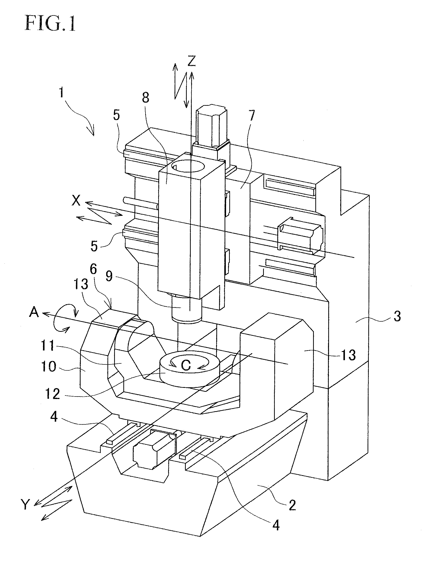
[0019]FIG. 1 shows a perspective view of a five-axis vertical machining center as an example of a machine tool. The vertical machining center 1 includes a bed 2 and a cross rail 3 having a double-column structure, and Y-axis guide rails 4, 4 are provided on an upper surface of the bed 2 and X-axis guide rails 5, 5 are provided on a front surface of the cross rail 3. An AC axis unit 6 having a trunnion structure as a table unit is installed on the Y-axis guide rails 4, 4 so as to be movable in a Y-axis direction. A ram saddle 7 is installed on the X-axis guide rails 5, 5 so as to be movable in an X-axis direction. A spindle head 8 having a spindle 9 at its lower end is installed on a front surface of the ram saddle 7 so as to be movable in a Z-axis direction.

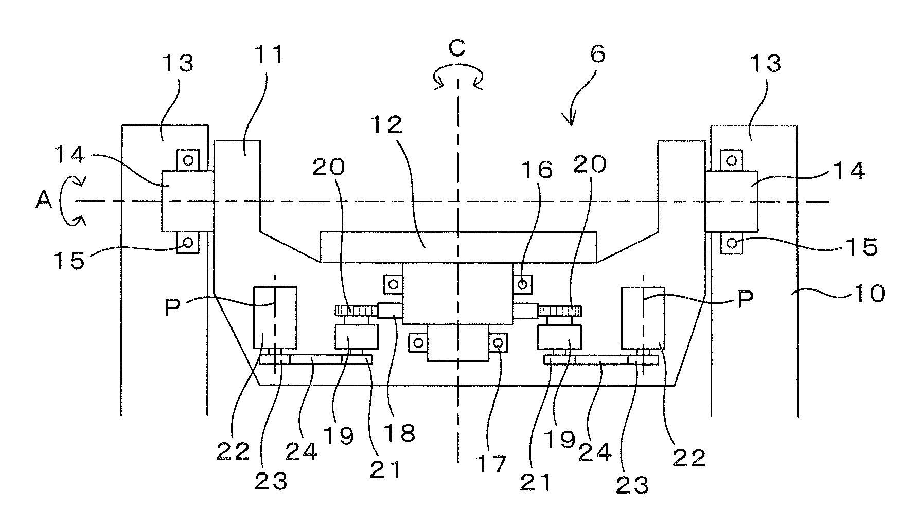
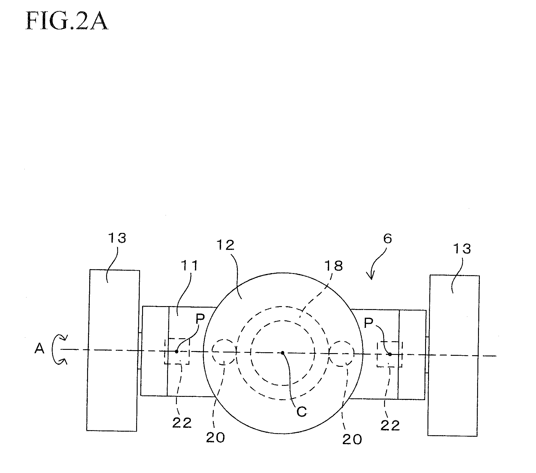
[0020]The AC axis unit 6 has a trunnion 11 as a tilting table on a base 10 which is movable on the bed 2 and h...


PUM

PropertyMeasurementUnit
speedaaaaaaaaaa
radius of swing rotationaaaaaaaaaa
driving forceaaaaaaaaaa

Abstract

A table unit for a machine tool includes a tilting table provided on a base and configured to be swingably indexable around a horizontal axis, a rotary table provided on the tilting table and configured to be rotatably indexable around a vertical axis orthogonal to the horizontal axis, and at least one motor disposed in the tilting table and configured to be driven to rotate the rotary table. An axis of a motor shaft of the motor is arranged in a plane formed by the horizontal axis and the vertical axis.

Description

BACKGROUND OF INVENTION[0001]This application claims the benefit of Japanese Patent Application Number 2011-097421 filed on Apr. 25, 2011, the entirety of which is incorporated by reference.FIELD OF THE INVENTION[0002]The present invention relates to a table unit for a machine tool, which comprises a tilting table swingably indexable around a horizontal axis, and a rotary table provided on the tilting table and rotatably indexable around a vertical axis orthogonal to the horizontal axis.DESCRIPTION OF RELATED ART[0003]A machine tool such as a vertical machining center has a bed, and a trunnion unit (AC axis unit) as a table unit provided on the bed. The trunnion unit includes a trunnion as a tilting table, which is provided on a base movable in the Y-axis direction along a Y-axis guide surface on the bed and is swingably indexable around an A-axis that is a horizontal axis parallel to an X-axis, and a rotary table provided on the trunnion and rotatably indexable around a C-axis that...

Claims


Application Information

Patent Timeline
Patent Type & Authority Patents(United States)
IPC IPC(8): B23Q1/48B23Q1/62B23C1/14B23Q3/04B23Q1/52
CPCB23Q1/621B23Q1/4857B23Q1/522Y10T409/305824Y10T408/5614Y10T409/307504Y10T409/305656B23Q1/5406B23Q1/5425
Inventor YOSHIDA, MAKOTO
Owner OKUMA CORP
Why Eureka
Try Eureka