Lens barrels

A lens barrel and lens technology, which is applied in installation, optics, instruments, etc., can solve the problems of lens barrel unit becoming larger and difficult, and achieve the effects of shortening the occupied distance, simplifying the device, and driving with high precision

Inactive Publication Date: 2007-09-19
ASIA OPTICAL CO INC +1
View PDF3 Cites 0 Cited by
  • Summary
  • Abstract
  • Description
  • Claims
  • Application Information

AI Technical Summary

Problems solved by technology

This type of focus drive device occupies the distance of the entire length of the focus motor plus the full length of the moving screw in the direction of the photographic optical axis. In the method of Patent Document 1, the focus drive device is arranged on the lens barrel for a thinner lens barrel. The inside of the cylinder is difficult
Therefore, like the embodiment of Patent Document 2, the focus driving device has to be arranged outside the lens barrel, and when the lens barrel unit is viewed from the front, there is a problem that the lens barrel unit becomes larger in plan.

Method used


Image

  • Lens barrels
  • Lens barrels
  • Lens barrels

Examples


Embodiment Construction

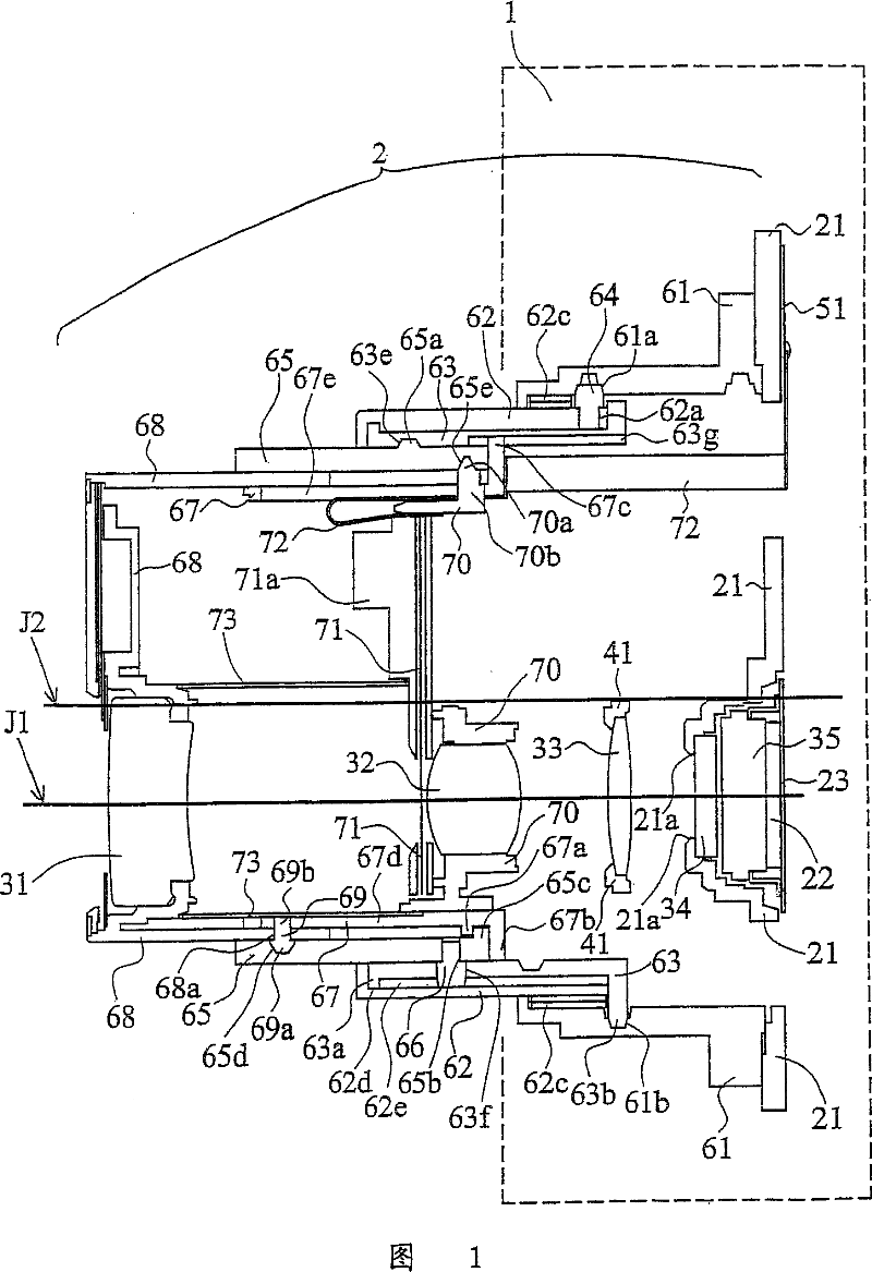
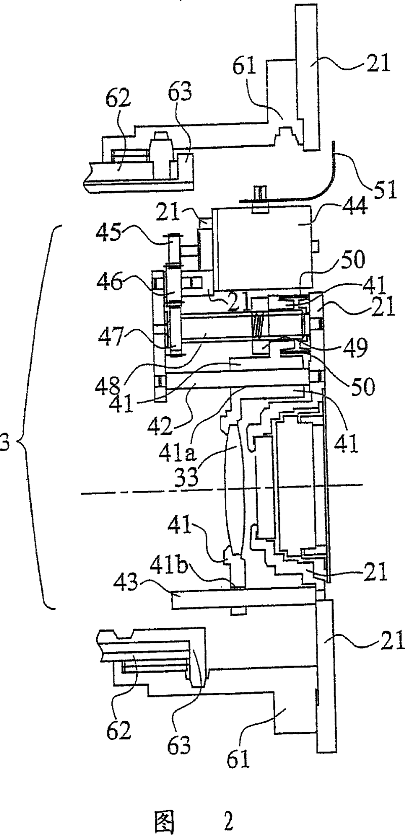
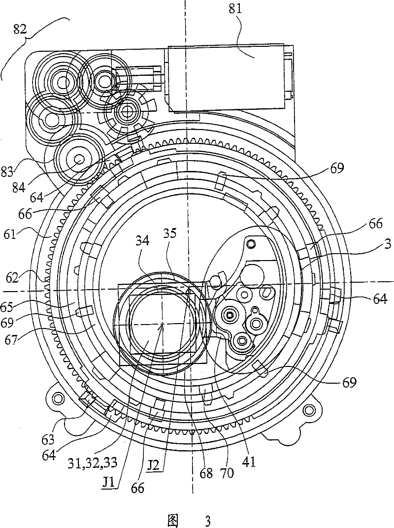
[0038] 1 to 21 illustrate the overall structure of the lens barrel of this embodiment. In this embodiment, the present invention is applied to a zoom lens barrel for a digital camera.

[0039] FIG. 1 is a cross-sectional view showing the lens barrel 2 in a shooting position on the wide-angle side. The photographing optical system is composed of a first lens group 31, a second lens group 32, a third lens group 33, a low pass filter (low pass filter) 34, and a CCD (photographic device) 35 in order from the subject side. . The optical axis of the photographic optical system is J1. The photographic optical axis J1 is parallel to the central axis J2 of the lens barrel, and is eccentric to the central axis J2. Zooming is performed by moving the first lens group 31 and the second lens group 32 in the direction of the imaging optical axis J1, and focusing is performed by moving the third lens group 33 in the direction of the imaging optical axis J1. Light beams passing through the...


PUM


Abstract

The invention provides a lens barrel. When a camera collapses the lens barrel, devices in the lens barrel can be efficiently arranged, so as to shrink the lens barrel. During photographing a picture, the lens barrel 2 adjusts the positions of a first lens group 31 and a second lens group 32 to a predetermined position in a photograph axis J1 to zoom. During collapsing the lens barrel, the first lens group 31 and the second lens group 32 are transferred to a side of a CCD 35 and a focus driving mechanism 3 to obtain a compact lens barrel. Since the focus driving mechanism 3 is disposed inside the lens barrel 2, the arrangement efficiency is enhanced and the planar arrangement is minimized.

Description

technical field [0001] The invention relates to a lens barrel for a sunken digital camera with a storage position and a shooting position. Background technique [0002] Recently, the demand for miniaturization of digital cameras has not stagnated. In particular, for the purpose of improving portability, more attention has been paid to the thinning of cameras. Therefore, thinning of the lens barrel unit is required to limit the thinning of cameras. It is known that as a method of reducing the thickness of the lens barrel unit, when not in use, the distance between the lens group and the imaging element is reduced, and the lens barrel is lowered to store it. [0003] In addition, in Patent Document 1 (Japanese Unexamined Patent Publication No. 2003-315861), in the stored state, a part of the photographic lens group is shifted from the photographic optical axis and pulled in to sink, so as to reach the lens mirror in the stored state. Thinning of the barrel. In addition, in P...

Claims


Application Information

Patent Timeline
Patent Type & Authority Patents(China)
IPC IPC(8): G02B7/04G02B7/10G02B15/14G03B5/00
CPCG02B7/102
Inventor 阪本宇正
Owner ASIA OPTICAL CO INC
Why Eureka
Try Eureka