Shutter apparatus, image pickup apparatus, and control method for the shutter apparatus

a control method and shutter technology, applied in the field of shutter apparatus, can solve the problems of inability to achieve faster shutter speed and lower shutter speed accuracy, and achieve the effect of high accuracy

Active Publication Date: 2019-12-10
CANON KK
View PDF5 Cites 3 Cited by
  • Summary
  • Abstract
  • Description
  • Claims
  • Application Information

AI Technical Summary

Benefits of technology

[0007]The present invention provides a shutter apparatus that can be highly accurately driven.

Problems solved by technology

Thus, due to the phase shift of the motor in this period from the ideal shift, the shutter speed accuracy lowers and a faster shutter speed cannot be realized.

Method used


Image

  • Shutter apparatus, image pickup apparatus, and control method for the shutter apparatus
  • Shutter apparatus, image pickup apparatus, and control method for the shutter apparatus
  • Shutter apparatus, image pickup apparatus, and control method for the shutter apparatus

Examples


first embodiment

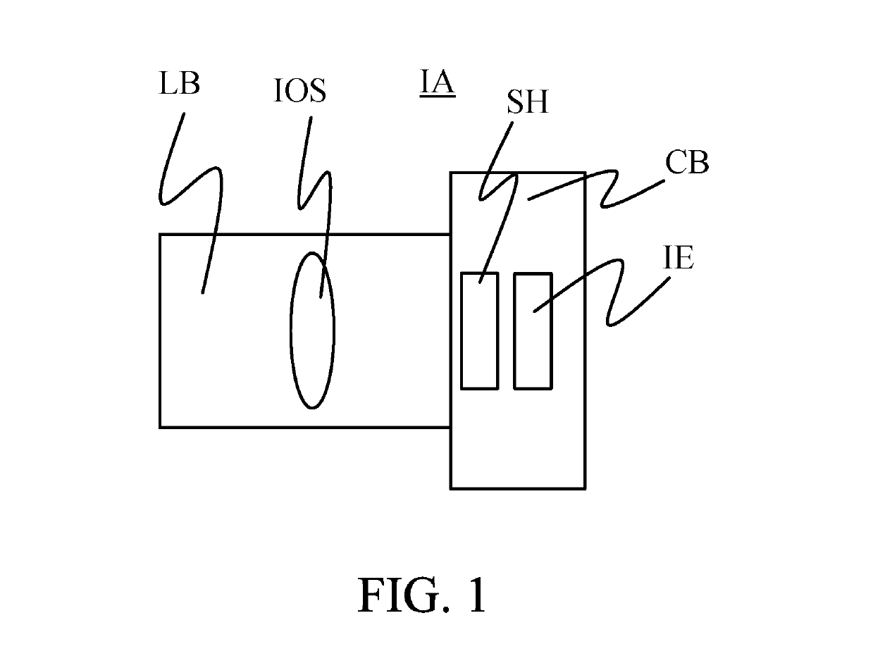
[0039]FIG. 1 is a schematic diagram of an image pickup apparatus IA that has a shutter apparatus SH according to an embodiment of the present invention. The image pickup apparatus IA includes a lens barrel LB configured to hold an image pickup optical system IOS, and a camera body CB configured to hold the shutter apparatus SH and an image pickup element or image sensor IE. The lens barrel LB may be attached to and detached from the camera body CB.

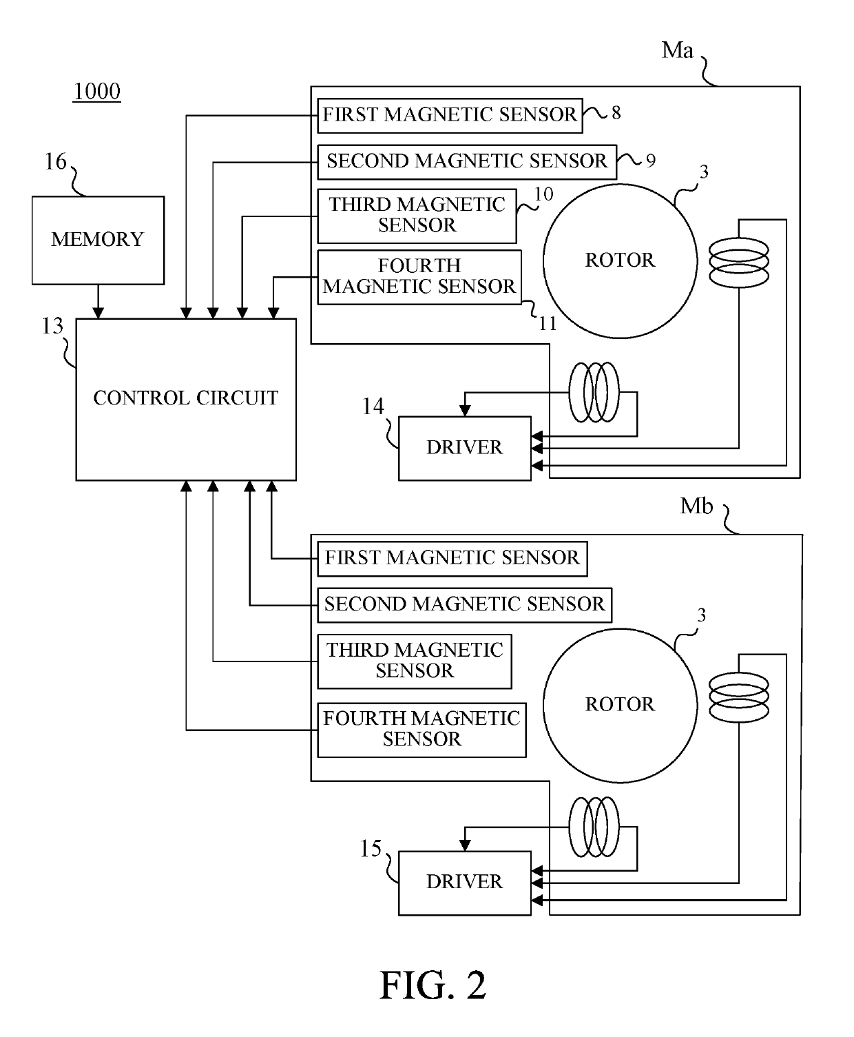
[0040]A detailed description will now be given of a drive controller 1000 for the shutter apparatus SH. FIG. 2 is a block diagram of the drive controller 1000. The drive controller 1000 includes motors Ma and Mb having the same structures, a control circuit (controller) 13, a motor driver (driver) 14 configured to electrify a coil in the motor Ma, a motor driver (driver) 15 configured to electrify a coil in the motor Mb, and a memory 16.

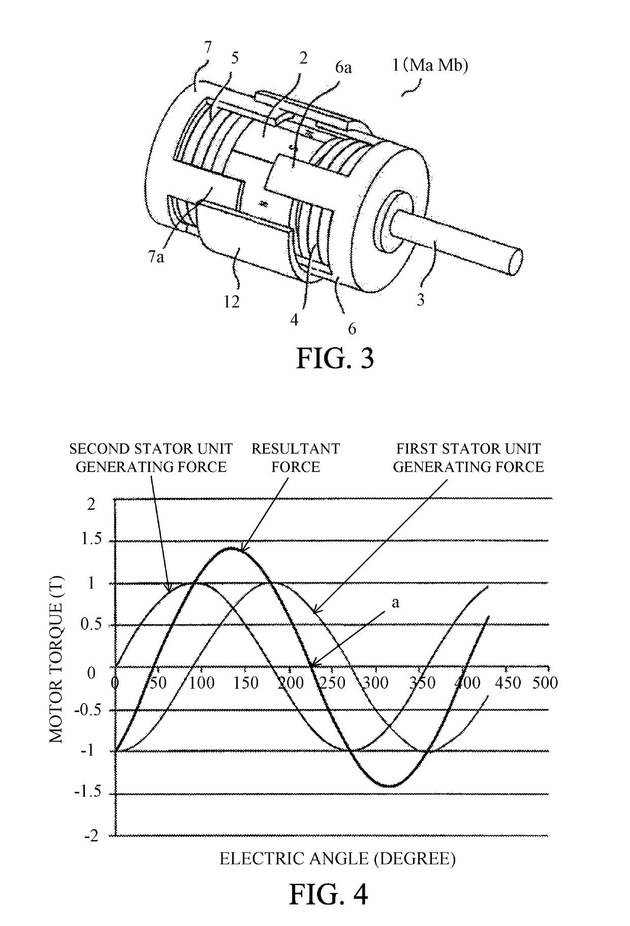
[0041]FIG. 3 is a perspective overview of the motor (Ma, Mb). For description purposes, FIG. 3 illustrat...

second embodiment

[0117]A focal plane shutter according to this embodiment has the same structure as that of the focal plane shutter according to the first embodiment, and a description of only the difference will be described.

[0118]The focal plane shutter according to this embodiment executes the micro step driving with an effective voltage Va and the full step driving with an effective voltage Vb lower than the effective voltage Va.

[0119]FIG. 27 illustrates a relationship between the number of steps and the electrified current in the coil when the micro step driving is switched to the full step driving at the timing “c” in FIG. 7.

[0120]Herein, the focal plane shutter according to the first embodiment uses the energy stored in the runup section to drive the blade unit, and thus the energy stored in the runup section is dominant for the shutter accuracy. Hence, even when the effective voltage Vb for the full step driving is set lower than the effective voltage Va for the micro step driving, the shutt...

third embodiment

[0123]A focal plane shutter according to this embodiment has the same structure as that of the focal plane shutter according to the first embodiment, and a description of only the difference will be described.

[0124]The focal plane shutter according to this embodiment executes the micro step driving with an effective voltage Va and the full step driving with an effective voltage Vc.

[0125]FIG. 28 illustrates a relationship between the number of steps and the electrified current in the coil when the micro step driving is switched to the full step driving at the timing “c” in FIG. 7.

[0126]If it is assumed that Vd is the effective voltage at the timing “c” in FIG. 7, the motor is driven with the effective voltage Vc equal to the effective voltage Vd in the full step driving.

[0127]When the micro step driving is switched to the full step driving and the current value abruptly changes, the driving force for driving the blade unit abruptly changes and the shutter accuracy may be affected. Ac...


PUM


Abstract

A shutter apparatus includes a motor, a cam gear, a driving member, and a blade group. A cam part includes a blade maintaining section configured to maintain one of an open state and a closed state of the blade group when a cam follower slides, and a blade driving section. Where the cam follower slides in the blade maintaining section and the blade driving section in this order, the motor is driven in the micro step driving mode when the cam follower slides in the blade maintaining section, and the motor is driven in the full step driving mode when the cam follower slides in the blade driving section.

Description

BACKGROUND OF THE INVENTIONField of the Invention[0001]The present invention relates to a shutter apparatus, an image pickup apparatus, and a control method for the shutter apparatus.Description of the Related Art[0002]A focal plane shutter is known as a shutter apparatus for a camera. The focal plane shutter operates a slit formed by two shutter blades (front and rear curtains) so as to continuously expose an image pickup plane. Each shutter blade reciprocates between a closed state that covers an opening in a shutter base plate and an open state that retreats and releases the opening.[0003]A cam member is rotated by driving a motor, this operation enables a cam follower to slide in a cam groove formed in the cam member, and each shutter blade can reciprocate between the closed state and the open state. The cam groove has a first cam area that enables the cam member to move without moving each shutter blade, a second cam area that drives each shutter blade from the closed state to ...

Claims


Application Information

Patent Timeline
Patent Type & Authority Patents(United States)
IPC IPC(8): G03B9/10H04N5/235G03B9/42H04N5/225
CPCG03B9/42G03B9/10H04N5/2353H04N5/2254H04N23/55H04N23/73
Inventor KARIBE, KAZUYAAOSHIMA, CHIKARATAKAYAMA, MASAHIRO
Owner CANON KK
Why Eureka
Try Eureka