Novel sterile filling valve

An aseptic filling and filling valve technology, which is applied in the field of beverage filling, can solve the problems of easy splashing, irregular liquid and non-concentration, and achieve the effect of avoiding splashing and reducing the generation of bubbles.

Inactive Publication Date: 2015-10-21
JIANGSU NEWAMSTAR PACKAGING MACHINERY
View PDF11 Cites 0 Cited by
  • Summary
  • Abstract
  • Description
  • Claims
  • Application Information

AI Technical Summary

Problems solved by technology

Although this structure plays a diversion role in the liquid filling process and reduces the generation of air bubbles, the liquid flowing out of the outlet is irregular, not concentrated, and easy to splash

Method used


Image

  • Novel sterile filling valve
  • Novel sterile filling valve
  • Novel sterile filling valve

Examples


Embodiment Construction

[0020] The technical solution of the present invention will be further explained below in conjunction with the drawings and specific embodiments.

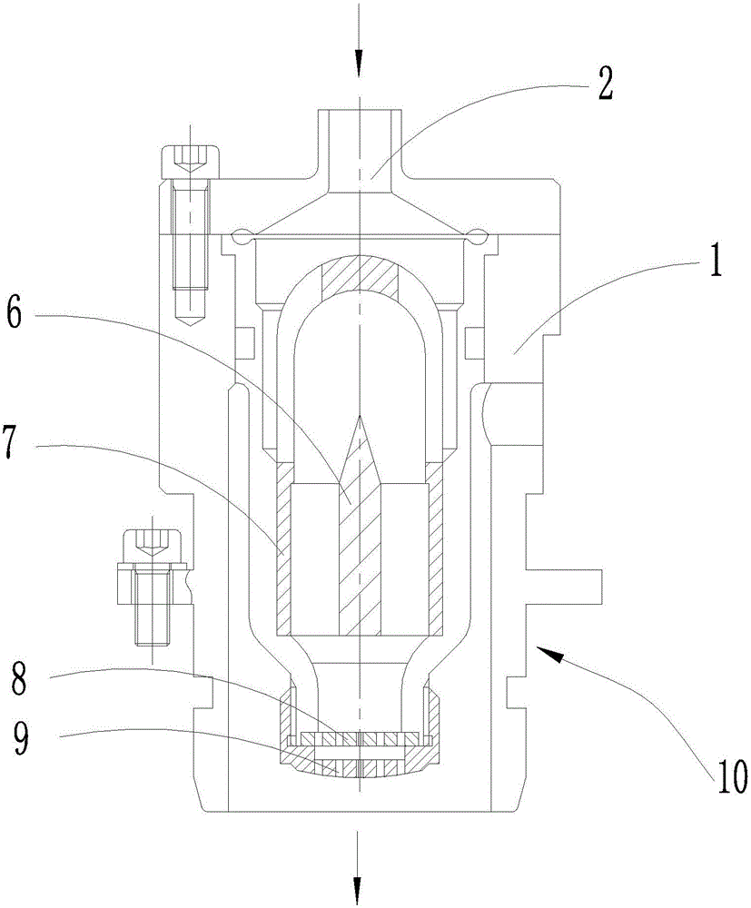
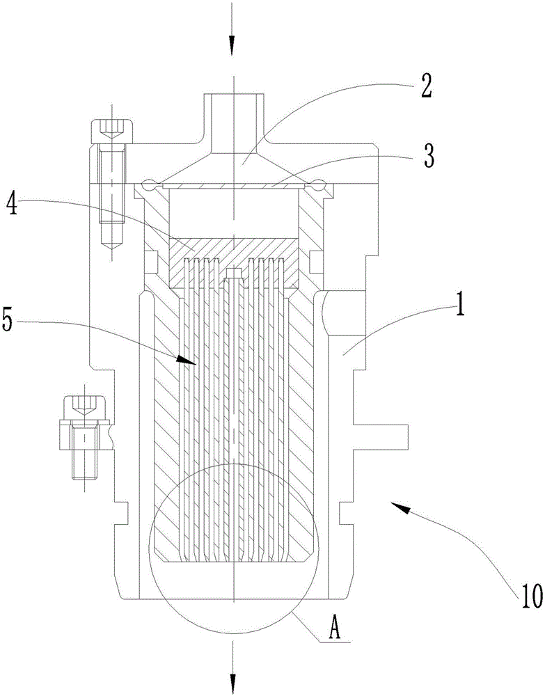
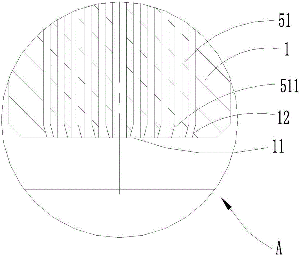
[0021] See figure 2 As shown, a new type of aseptic filling valve 10 includes a valve body with an inner cavity 1, a feed pipe arranged at the upper end of the valve body 1 and communicating with the inner cavity of the valve body 1, an outlet arranged at the bottom of the valve body 1. The filling port 11, the filling valve 10 also includes a diverter plate 3 provided with a diverging hole in the inner cavity of the valve body 1, and a valve core 5 provided below the diverter plate 3 for diversion of the material to be filled, The bracket 4 for installing the valve core 5 is located between the splitter plate 3 and the valve core 5. Here, the outer peripheral side wall of the splitter plate 3 can be sealed with the cavity wall of the inner cavity of the valve body 1, and the length of the bracket 4 is The two ends of the direction ...


PUM

PropertyMeasurementUnit
Angleaaaaaaaaaa

Abstract

The invention discloses a novel sterile filling valve. The novel sterile filling valve comprises a valve body with an inner cavity, a feeding pipe arranged at the upper end of the valve body and communicated with the inner cavity of the valve body and a discharging port formed in the bottom of the valve body, and the filling valve further comprises a splitter plate arranged in the inner cavity of the valve body, a valve core located below the splitter plate and a support located between the splitter plate and the valve core, wherein splitter holes are formed in the splitter plate, and the support is used for allowing the valve core to be installed therein, the valve core comprises a plurality of guide cylinders with different diameters, the guide cylinders are arrayed in the radial direction, reverse foot portions are arranged at the bottom ends of the side walls of parts of all the guide cylinders including the guide cylinder at the outermost side, and the diameters of the reverse foot portions decrease gradually in the direction close to the discharging direction of the discharging port. The novel sterile filling valve has the advantages that the structure is simple, the machining required precision is low, the production cost is low, through the arrangement of the reverse foot portions, the liquid flowing out from the discharging port is more regular and centralized, and liquid splashing and the occurrence of foams are effectively avoided.

Description

technical field [0001] The invention relates to the field of beverage filling, in particular to a novel aseptic filling valve. Background technique [0002] Aseptic filling generally adopts the filling method of non-contact bottle mouth, which requires no dead angle and easy cleaning. And in the filling process, it is required to reduce the generation of air bubbles, and there should be no liquid splashing. The structure of the current filling valve is as follows: figure 1 As shown, it is mainly composed of a shunt core 6, a slow flow cap 7, a filter screen 8 and a valve cover 9. Although this structure plays a diversion role in the liquid filling process and also reduces the generation of air bubbles, the liquid flowing out of the outlet is irregular, not concentrated, and easy to splash. Contents of the invention [0003] The purpose of the present invention is to provide a new type of aseptic filling valve, which can not only divert the filled liquid, reduce the ...

Claims


Application Information

Patent Timeline
IPC IPC(8): B67C3/28
CPCB67C3/26B65B39/00
Inventor 姚玲邹中全
Owner JIANGSU NEWAMSTAR PACKAGING MACHINERY
Why Eureka
Try Eureka