Rib plate type retaining wall and construction method thereof

A technology of retaining walls and ribs, which is applied in construction, underwater structures, infrastructure engineering, etc., can solve problems such as uneconomical, self-heavy, and large wall sectional volume, so as to reduce the workload of excavation, The effect of reducing the amount of temporary support works and improving construction safety

Active Publication Date: 2015-10-21
SOUTHWEST JIAOTONG UNIV
View PDF5 Cites 5 Cited by
  • Summary
  • Abstract
  • Description
  • Claims
  • Application Information

AI Technical Summary

Problems solved by technology

However, in engineering practice, the gravity retaining wall also has the following problems: (1) During the construction of the gravity retaining wall, the slope soil is first excavated from top to bottom, and then the wall is built or poured from the bottom to the top. When the wall is high, the entire excavation face will be large and steep, which will cause strong unloading disturbance to the original slope soil, which will easily lead to slope collapse during construction, especially in the deep cutting section; ( 2) The gravity retaining wall relies on its own gravity to maintain balance and stability, so it is self-heavy and has high requirements for the bearing capacity of the foundation. Construction on soil foundations is often limited by the bearing capacity; (3) When the retaining wall is high, the wall cut-off Large volume, large amount of masonry, uneconomical

Method used


Image

  • Rib plate type retaining wall and construction method thereof
  • Rib plate type retaining wall and construction method thereof

Examples


Embodiment

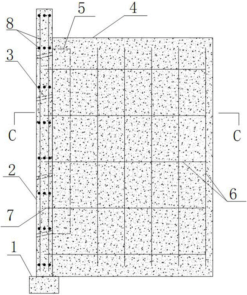
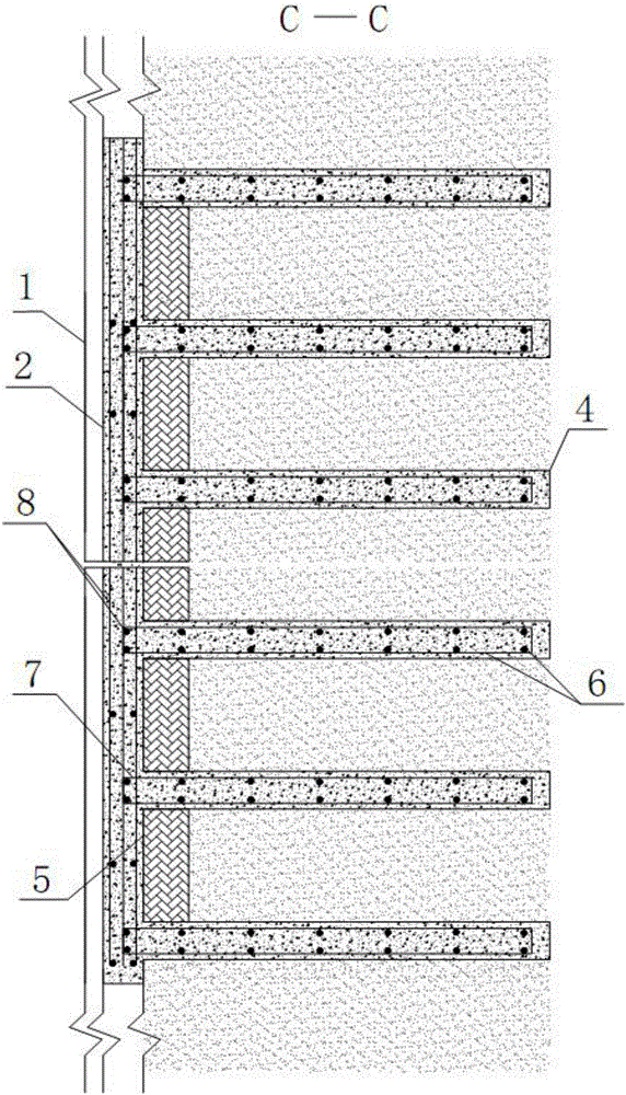
[0024] figure 1 , figure 2 It is shown that a specific embodiment of the present invention is a ribbed retaining wall, comprising a foundation 1, a wall panel 2 on the foundation 1, and a drain hole 3 on the wall panel 2, and its structural characteristics are as follows: The wall panel 2 facing the soil surface is consolidated with vertical ribs 4 at equal intervals, and the part of the wall panel 2 facing the soil surface between the ribs 4 is provided with an anti-filter layer 5 .

[0025] A construction method of the ribbed retaining wall of this example, the steps are:

[0026] a. Excavate a vertical groove matching the rib plate 4 in the slope soil body;

[0027] b. Bind the rib plate steel bar 6 in the vertical groove of step a and reserve the connecting steel bar 7 connecting the wall panel, then pour concrete in the vertical groove to form the rib plate 4 of the exposed connecting steel bar 7;

[0028] c. Excavate the foundation groove of the wall panel 2, and bui...


PUM


Abstract

The invention provides a rib plate type retaining wall and a construction method thereof. The retaining wall comprises a foundation, a wall panel on the foundation and drain holes in the wall panel. The retaining wall is structurally characterized in that vertical rib plates are fixedly connected to the soil adjacent face of the wall panel at equal intervals, and an inverter filter is arranged at the portion, between the rib plates, of the soil adjacent face of the wall panel. The construction method of the retaining wall includes the steps that a, vertical grooves matched with the rib plates are dug in slope soil mass; b, rib plate rebars are bound into the vertical grooves in the step a, connecting rebars connected with the wall panel are reserved, and concrete is poured into the vertical grooves to form the rib plates; c, the foundation is constructed; d, wall panel rebars are bound to the foundation, the wall panel rebars and the connecting rebars are connected, a wall panel formwork is erected, drain hole pipes are embedded, and concrete is poured into the wall panel formwork to form the wall panel; e, the inverted filter is laid at the portion, between the rib plates, of the soil adjacent face of the wall panel, and soil mass is backfilled between the inverted layer and a slope and compacted till the wall top. The retaining wall is suitable for supporting and retaining steep slopes or embankment sections or cutting steep slope sections, and is low in construction cost and easy to popularize.

Description

technical field [0001] The invention relates to a slope retaining wall and a construction method thereof, in particular to a retaining wall suitable for supporting and retaining a steep slope, an embankment section or a steep slope section of a road cutting and a construction method thereof. Background technique [0002] Retaining structures, including retaining walls, anti-sliding (anchor) piles, anchor cables (rods) and other structural forms, are used to support, reinforce fill or slope soil, and prevent collapse to maintain its stability. things. The retaining wall is the most commonly used retaining structure in engineering construction. It is mainly used to support the embankment fill or slope soil, prevent the fill or soil from being deformed and unstable, and bear the lateral earth pressure of the soil. Its uses mainly include : (1) reduce the excavation slope height, reduce the amount of excavation, and avoid the instability and landslide of the mountain; (2) shrin...

Claims


Application Information

Patent Timeline
Patent Type & Authority Applications(China)
IPC IPC(8): E02D29/02
Inventor 罗强张玉广蒋良潍张良姚阳刘刚谢涛连继峰宋鑫洛飞
Owner SOUTHWEST JIAOTONG UNIV
Why Eureka
Try Eureka