Axial permanent magnet spherical surface magnetic levitation flywheel motor

A flywheel motor and magnetic levitation technology, applied in magnetic circuits, electric components, electrical components, etc., can solve problems such as strong gyroscopic effect of vehicle installation space, vehicle driving environment, difficulty in motor analysis and high-speed control, and complex electromagnetic strong coupling relationship of motors. , to achieve the effect of satisfying the gyro effect suppression and improving the utilization of axial space and improving the standby time

Pending Publication Date: 2019-07-12
NANJING INST OF TECH
View PDF9 Cites 2 Cited by
  • Summary
  • Abstract
  • Description
  • Claims
  • Application Information

AI Technical Summary

Problems solved by technology

However, looking at home and abroad, the current practical engineering application of magnetic levitation motors is not very popular. The main reason is that there is a complex electromagnetic strong coupling relationship between the internal winding-magnetic circuit-electromagnetic force of the motor, and the analysis and high-speed control of the motor are difficult. This has become the main bottleneck restricting this technology from entering engineering applications
At the same time, it is used for vehicle flywheel batteries. The limited vehicle installation space and complex vehicle driving environment and road conditions make it face strong gyro effect, external disturbance interference and reliability problems.

Method used


Image

  • Axial permanent magnet spherical surface magnetic levitation flywheel motor
  • Axial permanent magnet spherical surface magnetic levitation flywheel motor
  • Axial permanent magnet spherical surface magnetic levitation flywheel motor

Examples


Embodiment Construction

[0027] In order to deepen the understanding of the present invention, the present invention will be described in further detail below in conjunction with the accompanying drawings and embodiments, which are only used to explain the present invention and do not limit the protection scope of the present invention.

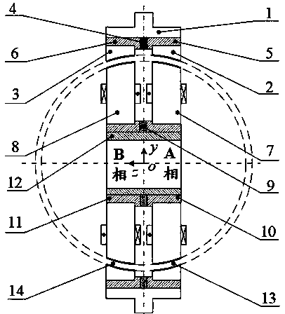
[0028] Such as figure 1As shown, an axial permanent magnet spherical magnetic levitation flywheel motor includes a flywheel 1, a rotor and a stator, and the rotor includes a rotor A phase spherical core 2, a rotor B phase spherical core 3, a rotor permanent magnet 4, and a rotor A phase magnetic ring 5 , Rotor B-phase magnetic ring 6; rotor A-phase spherical core 2, rotor B-phase spherical core 3 are respectively fixed on the outer sides of rotor A-phase magnetic ring 5, rotor B-phase magnetic ring 6, rotor A-phase magnetic ring 5 and rotor The rotor permanent magnet 4 is sandwiched between the B-phase magnetic ring 6, the rotor permanent magnet 4, the rotor A-phase ...


PUM


Abstract

The invention relates to an axial permanent magnet spherical surface magnetic levitation flywheel motor, belonging to the technical field of magnetic levitation motors. The axial permanent magnet spherical surface magnetic levitation flywheel motor comprises a flywheel, a rotor and a stator. The flywheel and the rotor form an integral body, the stator and the rotor are divided into an A phase anda B phase in an axial direction, and axial reverse magnetizing permanent magnets are respectively clamped between a rotor A-phase magnetic conducting ring and a rotor B-phase magnetic conducting ringand between a stator A-phase magnetic conducting ring and a stator B-phase magnetic conducting ring; the rotor comprises a rotor A-phase spherical surface iron core, a rotor B-phase spherical surfaceiron core, a rotor permanent magnet, the rotor A-phase magnetic conducting ring and the rotor B-phase magnetic conducting ring; the stator comprises a stator A-phase spherical surface iron core, a stator B-phase spherical surface iron core, a stator permanent magnet, the stator A-phase magnetic conducting ring, the stator B-phase magnetic conducting ring and a stator sleeve; each-phase stator spherical surface iron core is provided with a wide-tooth suspension poles, narrow-tooth torque poles and magnetic isolating bodies, and the suspension poles and the torque poles employ pole shoe structures and are respectively wound with suspension control coils and torque control coils. The axial permanent magnet spherical surface magnetic levitation flywheel motor improves the global uniformity ofair gap magnetic density, achieves the shaftless support of the flywheel and inhibits the gyroscopic effect; meanwhile, the system integration level, the operation efficiency and the reliability are improved, and the decoupling of the suspension magnetic circuit and the torque magnetic circuit is achieved.

Description

technical field [0001] The invention discloses an axial permanent magnet spherical magnetic suspension flywheel motor, which belongs to the technical field of magnetic suspension motors. Background technique [0002] Due to energy and environmental issues, electric vehicles are developing at an unprecedented rate. Power batteries are the source of power and a key factor restricting the development of electric vehicles. As an independent power source, it is difficult for the battery to meet the charging and discharging engineering requirements of the vehicle's frequent start and stop instantaneous high power (the peak power required for the vehicle to start and accelerate is 30 times that of the constant speed driving), and its performance and life are affected by the vehicle's operating environment temperature, charge and discharge depth and cycle limits. Flywheel batteries are highly valued at home and abroad for their advantages of high frequency and high power, energy sa...

Claims


Application Information

Patent Timeline
Patent Type & Authority Applications(China)
IPC IPC(8): H02K1/27H02K1/24H02K1/17H02K1/14H02K3/28H02K7/02H02K7/09
CPCH02K1/2786H02K1/24H02K1/17H02K1/146H02K3/28H02K7/025H02K7/09H02K2201/03Y02E60/16
Inventor 朱志莹孙玉坤朱金郭旋周家豪姚致勋
Owner NANJING INST OF TECH
Why Eureka
Try Eureka