Coal cutter body unit with adjustable height
An adjustable and shearer technology, applied in the direction of earthwork drilling, cutting machinery, etc., can solve the problems of low coal recovery rate and impact on coal quality, and achieve the effects of low manufacturing and use costs, simple structure, and convenient maintenance
- Summary
- Abstract
- Description
- Claims
- Application Information
AI Technical Summary
Problems solved by technology
Method used
Image

Examples
Embodiment 1
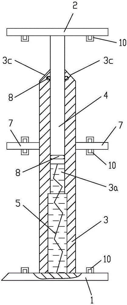
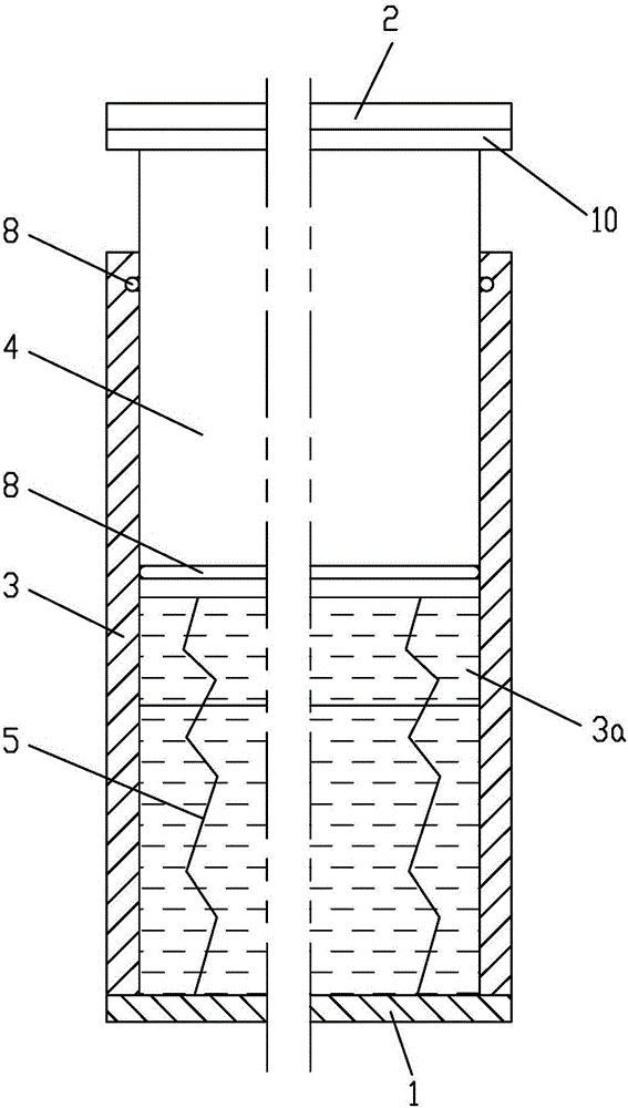
[0023] Example 1 see figure 1 , figure 2 , a height-adjustable shearer fuselage unit, an integrated coal mining and transporting machine for horizontal or near-horizontal propelling continuous lateral coal cutting and coal transportation, including a horizontally arranged bottom plate 1 and top plate 2, and bottom plate 1 and top plate 2 The wall panel is connected into an I-shaped frame; the two sides of the wall panel body 3 are fixedly connected with horizontal partitions 7, and the two horizontal partitions 7 separate the frame into a king shape, thereby forming a double-layer coal cutting area distributed up and down, and the top plate 2 The lower end surface, the upper end surface of the bottom plate 1 and the upper and lower ends of the horizontal partition 7 are provided with annular guide rails 10, and the two guide rails 10 in the coal cutting area of the same layer are used for the circular movement guide of the same chain plate; The main body 3 and the telescop...
Embodiment 2
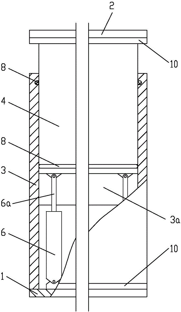
[0025] Example 2, see image 3 , the hydraulic lifting device is formed by at least two pressure cylinders 6, the free end of the piston rod 6a of the pressure cylinder 6 is hinged at the lower end of the cuboid part of the telescopic body 4, and the cylinder bottom ends of the two pressure cylinders 6 are hinged on the bottom plate 1 superior. Wherein, the two sealing rings 8 are used to prevent the sliding fitting section between the telescopic body 4 and the wallboard body 3 from being polluted by dust, so as to eliminate or slow down abnormal wear and prolong the service life. Wherein, the quantity of the pressure oil cylinder 6 is determined according to factors such as the length of the fuselage unit and the size of the pressure oil cylinder 6 .
[0026] The rest of the structure of this embodiment is the same as that of Embodiment 1, and will not be repeated here.
Embodiment 3
[0027] Example 3, see Figure 4 , Figure 5 , the only telescopic combination structure is formed by sliding fit of at least two circular column hole matching structures; wherein, the circular column hole matching structure includes at least two round holes 3b provided on the wallboard body 3, and the telescopic body 4 includes at least two cylindrical parts corresponding to the round holes 3b one by one; the hydraulic lifting device is formed by the same number of pressure cylinders 6 as the cylinder parts, and the piston rods 6a of the pressure cylinders 6 are hinged one by one. The lower end of the cylindrical part of the telescopic body 4 and the cylinder body of the pressure oil cylinder 6 are hinged on the base plate 1 . Wherein, the quantity of the pressure oil cylinder 6 is determined according to factors such as the length of the fuselage unit and the pressure oil cylinder 6; the cylindrical section of the expansion body 4 and the round hole 3b on the wallboard body ...
PUM
 Abstract
Description
Claims
Application Information
 - Generate Ideas
- Intellectual Property
- Life Sciences
- Materials
- Tech Scout
- Unparalleled Data Quality
- Higher Quality Content
- 60% Fewer Hallucinations
Browse by: Latest US Patents, China's latest patents, Technical Efficacy Thesaurus, Application Domain, Technology Topic, Popular Technical Reports.
© 2025 PatSnap. All rights reserved.Legal|Privacy policy|Modern Slavery Act Transparency Statement|Sitemap|About US| Contact US: help@patsnap.com