Input voltage sharing control method of modularized combined direct-current converter

A DC converter and voltage equalization control technology, which is applied in the direction of converting DC power input to DC power output, control/regulation systems, instruments, etc., can solve the problems of unstable output characteristics of modular DC converters, and meet the requirements of modularization. Design needs, the effect of simple controller design

Inactive Publication Date: 2015-10-21
HARBIN INST OF TECH
View PDF5 Cites 11 Cited by
  • Summary
  • Abstract
  • Description
  • Claims
  • Application Information

AI Technical Summary

Problems solved by technology

[0007] The purpose of the present invention is to solve the problem of unstable output characteristics of the existing modular DC converters, and the present invention provides a method for controlling input voltage equalization of modular combined DC converters

Method used


Image

  • Input voltage sharing control method of modularized combined direct-current converter
  • Input voltage sharing control method of modularized combined direct-current converter
  • Input voltage sharing control method of modularized combined direct-current converter

Examples


specific Embodiment approach 1

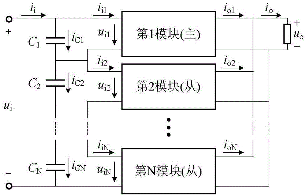
[0037] Specific implementation mode one: combine figure 1 and figure 2 Describe this implementation mode, the input voltage equalization control method of the modularized combined DC converter described in this implementation mode, for such as figure 1 The input series output parallel DC converter system shown, u i i i Total input voltage and total input current, respectively, i o , u o are the system output voltage and output current respectively, u i1 ~ u iN i i1 ~i iN i o1 ~i oN are the input voltage, input current and output current of each module respectively, i c1 ~i cN Input voltage dividing capacitor current for each module respectively.

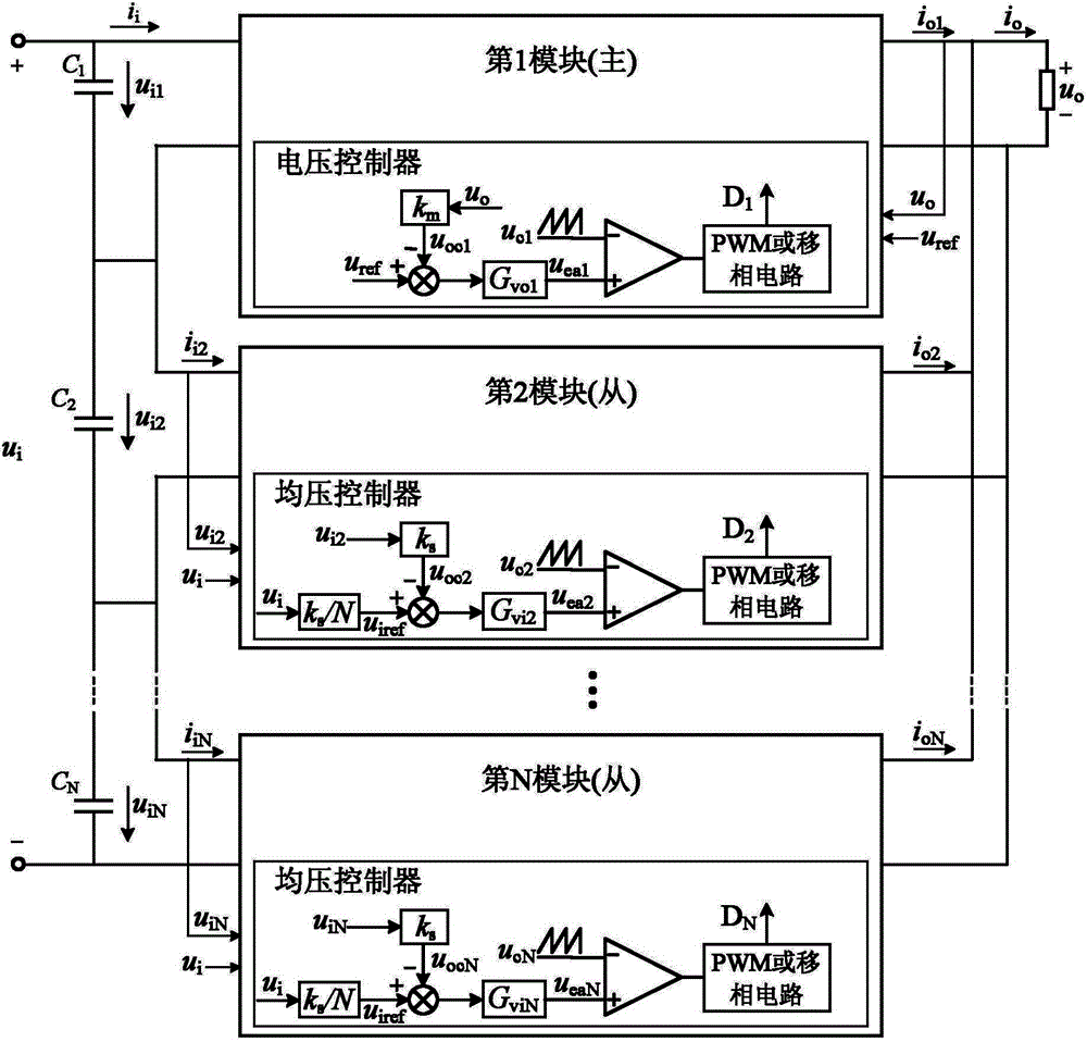
[0038] This embodiment is suitable for controlling the constant voltage output of the Input Series Out Parallel-ISOP combined converter system. For the ISOP system with constant voltage output, among the N modules in the system, the first module is set as the main module , the remaining modules are slave modules, such a...

specific Embodiment approach 2

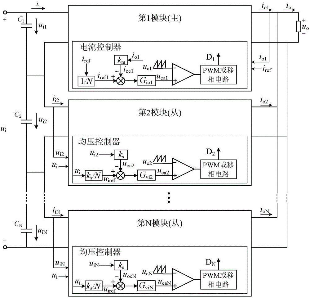
[0047] Specific implementation mode two: combination figure 1 and image 3 Describe this embodiment, a method for controlling input voltage equalization of a modular combined DC converter described in this embodiment, this embodiment is suitable for controlling the constant current output of an input series output parallel (Input Series Out Parallel-ISOP) combined converter system , for the ISOP system with constant current output, among the N modules in the system, the first module is set as the master module, and the remaining modules are slave modules, such as image 3 As shown, each module includes a corresponding controller; the main module, that is, the first module adopts a current controller, and the output current i of the first module is o1 As feedback, 1 / N of the total output current is used as a given, and the output current of the first module is guaranteed to be 1 / N of the total current through the control function. The specific implementation method is:

[004...


PUM


Abstract

The invention, which belongs to the technical field of the high-frequency switching transformer direction, provides an input voltage sharing control method of a modularized combined direct-current converter. With the method, a problem of the unstable output characteristic of the modularized combined direct-current converter can be solved. The method is suitable for controlling the voltage-constant output or current-constant output of the input-series-output-parallel (ISOP) combined converter system. N modules are arranged in the system, wherein the N is a positive integer larger than 1; and the first module is set as a master module and the rest of modules are set as slave modules. Feedback control is carried out on the output voltage or output current of the master module to control the total output voltage or total output current of the system, thereby realizing the voltage-constant output or current-constant output of the system; and input voltages of all slave modules are controlled to guarantee input voltage sharing of the system.

Description

technical field [0001] The invention belongs to the technical field of high-frequency switching converters. Background technique [0002] Electric energy is the most important form of energy in today's era, and the transformed and appropriate electric energy supply is a prerequisite for the smooth progress of social production and life. In the field of power electronics technology for the study of electric energy conversion, switching converters have attracted attention due to their high efficiency and have always been the focus of research. Switching converters have penetrated into various fields of production and life and are widely used. With the advancement of technology, switching converters are developing in the direction of high frequency, modularization, intelligence, and digitization. [0003] In the case of medium and high input voltage (greater than 1kV), the main problem faced by the DC converter is that the voltage stress of the switching device is high, and a ...

Claims


Application Information

Patent Timeline
Patent Type & Authority Applications(China)
IPC IPC(8): H02M3/00
Inventor 杨威杨世彦张智杰韩基业
Owner HARBIN INST OF TECH
Why Eureka
Try Eureka