
Antenna selection method based on massive MIMO system

An antenna selection, large-scale technology, applied in transmission systems, radio transmission systems, diversity/multi-antenna systems, etc., can solve problems such as high complexity, and achieve the effect of reducing complexity and preserving performance

Active Publication Date: 2015-10-21
XI AN JIAOTONG UNIV
View PDF6 Cites 9 Cited by
  • Summary
  • Abstract
  • Description
  • Claims
  • Application Information

AI Technical Summary

Problems solved by technology

[0005] Both of the above two low-complexity suboptimal algorithms require iteration, and the channel capacity is continuously calculated during the iteration process. For a massive MIMO system with a large base of alternative antennas, the complexity is still very large

Method used


Image

  • Antenna selection method based on massive MIMO system
  • Antenna selection method based on massive MIMO system
  • Antenna selection method based on massive MIMO system

Examples


Embodiment Construction

[0026] The present invention will be described in detail below in conjunction with the accompanying drawings and embodiments.

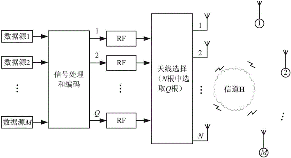
[0027] The system model applicable to the method of the present invention can be found in figure 1 . Consider the scenario of a downlink single-cell multi-user MIMO system: the base station is configured with N service antennas and Q radio frequency links, and serves M single-antenna users at the same frequency at the same time, where M≤Q≤N, such as figure 1 shown in . It is assumed that the base station can obtain complete channel state information from the base station to all serving users. Based on the complete channel state information and according to the criterion of maximizing the channel capacity, Q so-called optimal antennas are selected from the N serving antennas. The selected Q antennas are connected to the Q radio frequency links one by one through the switch.

[0028] first, Indicates the set of all candidate service antennas, excl...


PUM


Abstract

The invention discloses an antenna selection method based on a massive MIMO system, comprising: 1) all users feeding complete channel state information to a base station; 2) based on the hypothesis that the power distribution of all selected antennas is uniform, calculating the channel capacity of each alternative antenna, and selecting an antenna with a largest channel capacity as a first selected antenna; and 3) based on the selection of the first antenna, and according to the related properties of a matrix space, continuously selecting antennas utilizing spatial domain resources to the most until the number of required antennas is realized. The method takes full advantage of a space free degree, possesses low complexity, is easy to realize, and maintains better system performance.

Description

technical field [0001] The invention relates to a wireless communication massive multiple-input multiple-output (Massive MIMO) system, in particular to an antenna selection method based on the massive MIMO system. Background technique [0002] Massive MIMO technology can significantly improve system performance. However, in an actual system, due to consideration of actual physical limitations and the complexity of implementing the system, the number of serving antennas at the base station cannot be arbitrarily increased to infinity. In addition, the cost of system implementation should also be considered. Adding more serving antennas to a base station is usually very cheap, and adding additional digital signal processing units is getting cheaper too. However, devices in the radio frequency (Radio Frequency, RF) link module, such as: RF low-noise amplifier, digital frequency up / down converter (Digital Frequency Up Converter, DUC / Digital Frequency Down Converter, DDC), analo...

Claims


Application Information

Patent Timeline
IPC IPC(8): H04B7/06
CPCH04B7/0608H04B7/061H04B7/0626
Inventor 任品毅赵兰奇杜清河孙黎
Owner XI AN JIAOTONG UNIV
Learn More