Diaphragm pump with a magnetohydrodynamic drive

A magnetic fluid dynamics and diaphragm pump technology, applied to pumps with flexible working elements, pumps, engine elements, etc., can solve the problems of inability to provide instantaneous flow rate measurement function, low efficiency, etc.

Inactive Publication Date: 2015-10-21
ВАСИЛЬЕВ, СЕРГЕЙ АЛЕКСАНДРОВИЧ
View PDF6 Cites 1 Cited by
  • Summary
  • Abstract
  • Description
  • Claims
  • Application Information

AI Technical Summary

Problems solved by technology

[0004] The disadvantage of this type of pump is the inefficiency caused by the mechanical drive and the need for periodic maintenance, which requires d

Method used


Image

  • Diaphragm pump with a magnetohydrodynamic drive
  • Diaphragm pump with a magnetohydrodynamic drive

Examples


example 1

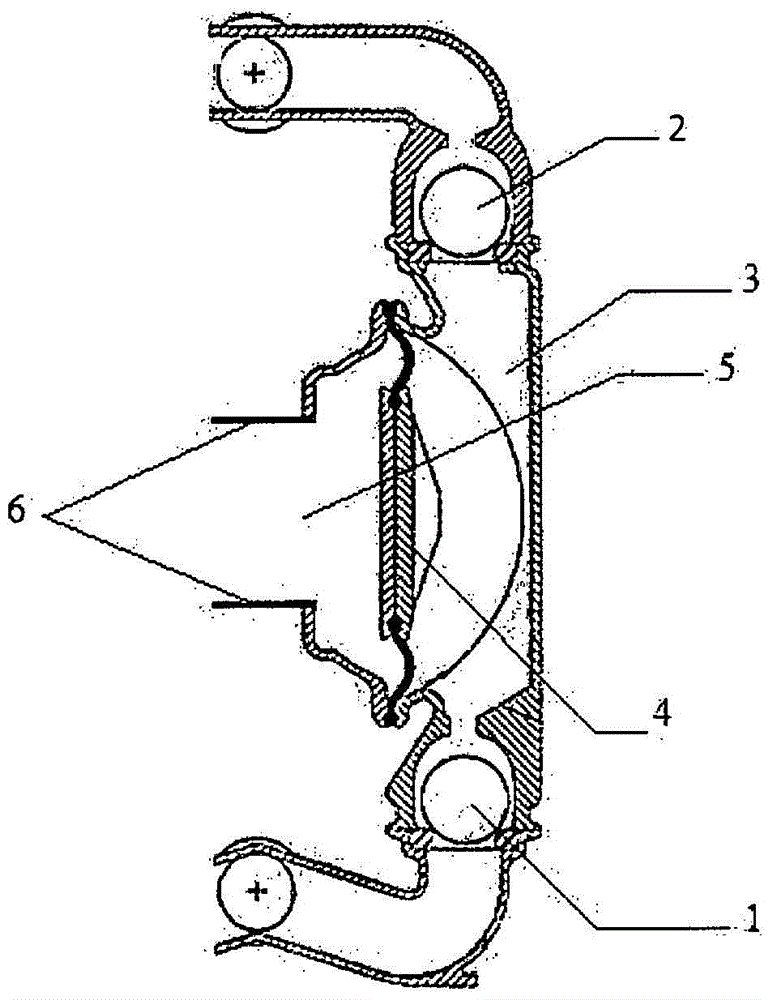
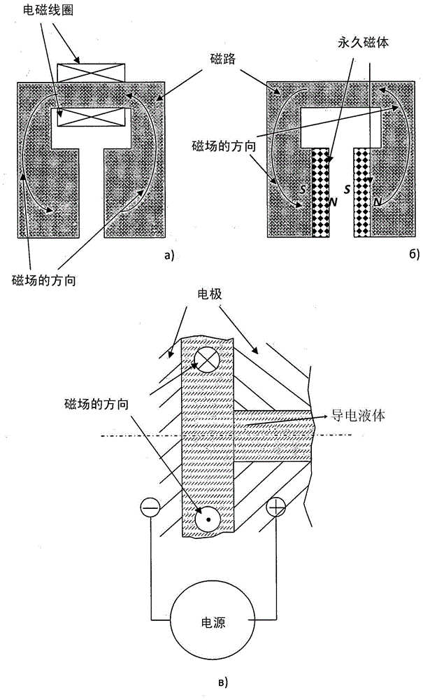
[0020] Example 1. The drive magnetic system generates a permanent magnetic field. In this case there are permanent magnets or electromagnetic coils, and a magnetic core with poles perpendicular to the electrodes 6 of the driven chamber 5 . The solenoid coils are powered from a DC power source. When using a permanent magnetic field, the reciprocating motion of the conductive liquid and of the driven membrane 4 is thus provided by an alternating current.

example 2

[0021] Example 2. The power supply is a DC power supply, which supplies DC power between the electrodes 6 of the driven chamber 5 . When direct current is used, the reciprocating motion of the driven diaphragm 4 is provided by the alternation of the magnetic field. The driving magnetic system comprises an electromagnetic coil and a magnetic core with magnetic poles perpendicular to the electrodes 6 of the driven chamber 5 . The electromagnetic coil is powered from its own AC power source. The alternating current in the electromagnetic coil provides an alternating field in the driven chamber 5 and thus the reciprocating motion of the conductive liquid and the driven membrane 4 .

example 3

[0022] Example 3. The power source is an AC power source, and an AC current is supplied between the electrodes 6 of the driven chamber 5 . The driving magnetic system comprises an electromagnetic coil and a magnetic core with magnetic poles perpendicular to the electrodes 6 of the driven chamber 5 . The electromagnetic coil is powered from its own AC power source. The combination of alternating current and alternating magnetic field makes the movement of the conductive liquid and the driven membrane 4 obey different laws, which can be used for special purposes.


PUM


Abstract

The utility model relates to the construction of pumps, in particular to diaphragm pumps, and can be used in various branches of engineering for pumping liquid or gaseous media. The diaphragm pump with the MHD drive comprises a minimum of one pumping section, comprising an inlet valve and an outlet valve and a working chamber with a driven diaphragm. Furthermore, the claimed pump additionally comprises a drive chamber which is separated from the working chamber by a driven diaphragm and is filled with current-conducting liquid, two opposite walls of which drive chamber are electrodes connected to a power source, and a controlling magnet system. Low-melting metals and/or alloys can be used as the current-conducting liquid. The use of this technical solution makes it possible remotely (without disassembly) to monitor the state of delivery elements of the device, and ensures a high degree of accuracy of metering the medium being pumped and minimization of energy losses in the drive mechanism.

Description

technical field [0001] The present invention relates to a pump, in particular a diaphragm pump (or diaphragm pump), and it can be used in different branches of the art of pumping gases and liquids. Background technique [0002] Said diaphragm pump is known (RU 4344 published on June 16, 1997), which comprises an intermediate chamber filled with a working fluid, said intermediate chamber having a driven diaphragm in communication with a mechanical piston. connect. The pump also has a pumping section, inlet and outlet valves, and a working chamber. The working chamber has a hydraulically driven membrane which acts as a boundary between the intermediate chamber and the working chamber and thus separates the working chamber from the intermediate chamber. [0003] The known pump works as follows. A mechanical piston coupled to a driven diaphragm reciprocates. When moving to the working chamber, the piston pulls the driven diaphragm, the liquid in the intermediate chamber, and...

Claims


Application Information

Patent Timeline
IPC IPC(8): F04B43/04H02K44/02
CPCH02K44/02F04B43/06F04B45/053F05C2251/12H02K44/04
Inventor S·A·瓦西列夫
Owner ВАСИЛЬЕВ, СЕРГЕЙ АЛЕКСАНДРОВИЧ
Why Eureka
Try Eureka